Apparatus and system for wide angle narrow-band optical detection in daylight

a wide-angle, narrow-band technology, applied in the direction of optical radiation measurement, fire alarm radiation actuation, instruments, etc., can solve the problems of high cost of ir detectors in such applications, insufficient daylight in the visible spectrum, and small fires in the wilderness can become forest fires

Active Publication Date: 2009-08-04
EDDY COMPANY THE +1
View PDF18 Cites 13 Cited by
  • Summary
  • Abstract
  • Description
  • Claims
  • Application Information

AI Technical Summary

Benefits of technology

[0015]Techniques are provided for narrowband wide-area optical filtering or detection of optical sources, or both, which do not suffer all the disadvantages of prior art approaches. These techniques allow the filter to be contained effectively within a compact wide angle (up to or greater than 100°) imaging system.
[0018]In some of these embodiments, the polarization-changing material is a metal vapor that rotates polarized light in the narrow wavelength band when subjected to a magnetic field. A heater is included to heat a particular component that contacts the metal vapor to prevent condensation of metal from the metal vapor onto the particular component.
[0019]In some of these embodiments, an inner chamber of walls that encloses the metal vapor is included. The walls of the inner chamber include a first inner optical window and a second inner optical window. The first inner optical window admits polarized light transmitted through the first polarizer; and the second inner optical window transmits light to impinge on the second polarizer. The heater is configured to heat the first inner optical window and the second inner optical window to prevent condensation of metal from the metal vapor onto the first inner optical window and the second inner optical window.

Problems solved by technology

For example, small fires in the wilderness can become forest fires that spread to populated areas.
Anti-aircraft missiles sent aloft by burning rocket fuel when launched by terrorists or enemy combatants often target civilian and military aircraft.
During the daylight hours, however, the visible spectrum is deluged by daylight, including direct sunlight, sunlight scattered from the sky and clouds, or sunlight reflected from objects on the ground or in the air.
The use of IR detectors in such applications is expensive.
Thus few private and commercial vehicles or aircraft are equipped with IR detectors.
In addition, processing IR images to determine what sources are of interest is complex and demands great processing power to reject clutter and various signatures that are not of interest.
The cost of the powerful processors adds to the cost of a system based on an IR detector.
The detectors and extensive processing lead to increased cost, size and weight of systems that rely on IR detectors.
The cold-cell MOFs, have a limited field-of-view, are bulky and need continuous calibration to guarantee long-term stability.
While prior implementations of the hot-cell, MOF can have a moderate field-of-view, they are difficult to construct in a way that minimizes polarization-inducing stresses in the cell windows and oven enclosure windows.
Furthermore, the hot cell filters require bulky ovens to maintain cell temperature and control vapor density.
Thus, conventional MOF implementations have a limited usefulness for monitoring large sections of earth or sky for fires, gunfire, missiles and other important combustion events.
Especially on aircraft, the total volume and weight available for a combustion monitoring system, such as a missile warning system, is limited.
A large array of narrow field of view cold cell MOFs, or hot-cell MOFs with bulky ovens are simply not feasible on an aircraft.

Method used


Image

  • Apparatus and system for wide angle narrow-band optical detection in daylight
  • Apparatus and system for wide angle narrow-band optical detection in daylight
  • Apparatus and system for wide angle narrow-band optical detection in daylight

Examples


Embodiment Construction

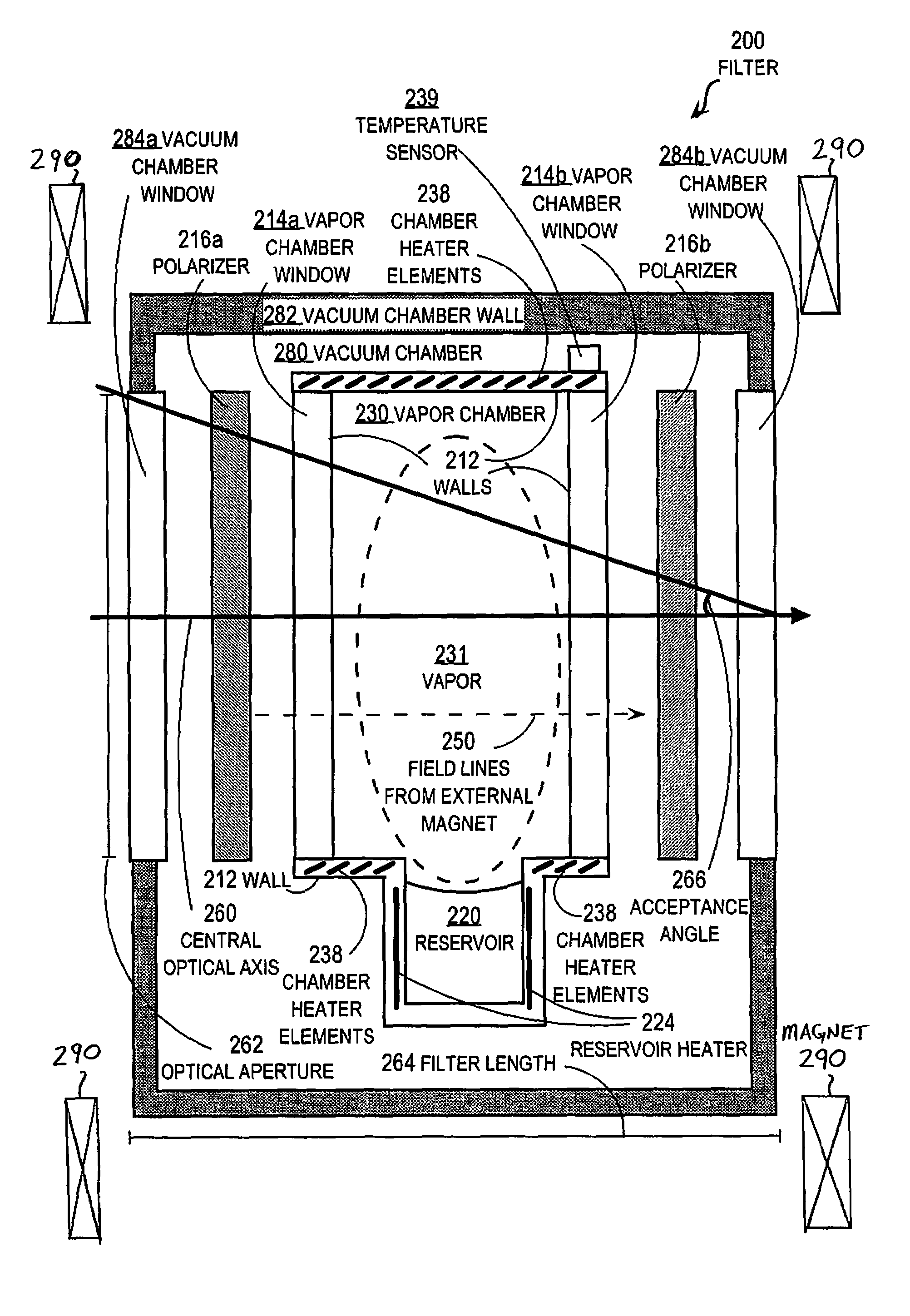
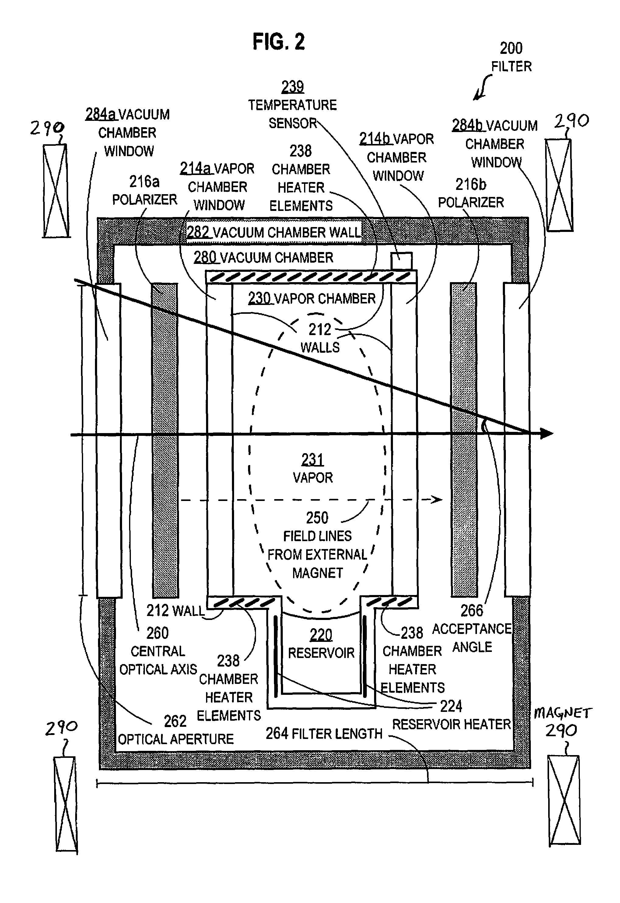
[0027]An apparatus and system are described for wide-view narrowband filtering and detection of optical sources. In the following description, for the purposes of explanation, numerous specific details are set forth in order to provide a thorough understanding of the present invention. It will be apparent, however, to one skilled in the art that the present invention may be practiced without these specific details. In other instances, well-known structures and devices are shown in block diagram form in order to avoid unnecessarily obscuring the present invention.

[0028]Some embodiments of the invention are descried below in the context of a Potassium vapor MOF in a vapor chamber enclosed in a vacuum chamber with heaters to avoid condensation in a filter having an optical aspect ratio of 4 to 1 or less. However, the invention is not limited to this context. In other embodiments, other materials, both in vapor and non-vapor states, serve to change polarization between the two polarizer...


PUM


Abstract

Techniques for filtering light include, along a central optical axis, an entrance window; a first polarizer, a narrowband polarization-changing material, a second polarizer, and an exit window. The optical paths through the filter are substantively unscattered and pass through unstressed components between the polarizers. The polarization-changing material changes polarization for a narrow wavelength band on the order of about 0.01×10⁻⁹ meters and does not condense on optical windows and polarizers during the operational lifetime. An aspect ratio, defined by a distance from the entrance window to the exit window divided by an optical aperture for the entrance window, is less than 4 / 1. This filter thus transmits light substantively unattenuated in the narrow wavelength band up to a maximum acceptance angle greater than 5 degrees. Combined with optics and imaging detectors, it is suitable for wide area surveillance, including daylight surveillance for combustion like forest fire and missile plume.

Description

CROSS-REFERENCE TO RELATED APPLICATIONS[0001]This application claims benefit of Provisional Appln. 60 / 695,274, filed Jun. 30, 2005, entitled “Narrow-Band Aircraft Missile Warning Sensor,” the entire contents of which are hereby incorporated by reference as if fully set forth herein, under 35 U.S.C. §119(e).[0002]This application also claims benefit of Provisional Appln. 60 / 748,464, filed Dec. 8, 2005, “Narrow-Band Aircraft Missile Warning Sensor,” the entire contents of which are hereby incorporated by reference as if fully set forth herein, under 35 U.S.C. §119(e).BACKGROUND OF THE INVENTION[0003]1. Field of the Invention[0004]The present invention relates to wide-angle narrowband optical filters with wavelength pass bands on the order of 0.01×10⁻⁹ meters in the visible range, and in particular to filters with fields of view in excess of 14 degrees suitable for detecting from an aircraft optical emissions from combustion in the presence of daylight.[0005]2. Description of the Relat...

Claims


Application Information

Patent Timeline
Patent Type & Authority Patents(United States)
IPC IPC(8): G02B27/28
CPCF41H11/02G01J3/00G01J5/0066G08B17/12G02B1/06G02B27/288G08B15/004G01J5/602G01J5/0018G01J5/089G01J2003/1213G01J5/07
Inventor RODGERS, WAYNEERLANDSON, ROBERT E.HARGIS, C. BRYONMURPHY, NEIL
Owner EDDY COMPANY THE
Why Eureka
Try Eureka