Rotation sensor with temperature measuring feature

a technology of rotating sensor and temperature measurement, which is applied in the direction of instruments, pulse techniques, fire alarms, etc., can solve the problems of increased component temperature, increased cost, and additional susceptibility to wear or damag

Inactive Publication Date: 2009-08-11
THE TIMKEN CO
View PDF8 Cites 8 Cited by
  • Summary
  • Abstract
  • Description
  • Claims
  • Application Information

AI Technical Summary

Benefits of technology

[0009]Briefly stated, the present invention provides a temperature sensing system for use with existing passive variable reluctance sensors, for example those associated with vehicle wheel bearings which utilizes an antilock braking system or traction control system, as a direct current resistive temperature gauge. The temperature sensing system further includes electrical components configured to separate the DC voltage representative of sensor temperature from the magnetically induced AC voltage output signals representative of the vehicle wheel speed, thereby permitting the temperature sensing system to be retrofitted and installed in vehicles without significant alteration to the vehicle wiring harness and electrical components, such as by insertion in between two connectors of an existing vehicle wiring harness.

Problems solved by technology

For example, a loss of lubricant or other cause of high friction, such as a contaminate or bearing failure, will result in an increase in component temperatures.
In addition to requiring a separate sensor disposed in the vehicle wheel bearing or housing, this classical solution requires a separate electrical circuit for the temperature sensor signals, resulting in an increase in cost and additional susceptibility to wear or damage.

Method used


Image

  • Rotation sensor with temperature measuring feature
  • Rotation sensor with temperature measuring feature
  • Rotation sensor with temperature measuring feature

Examples


embodiment 100

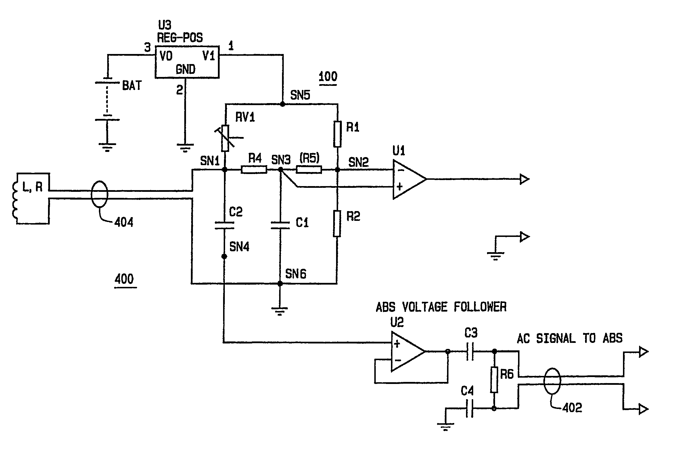
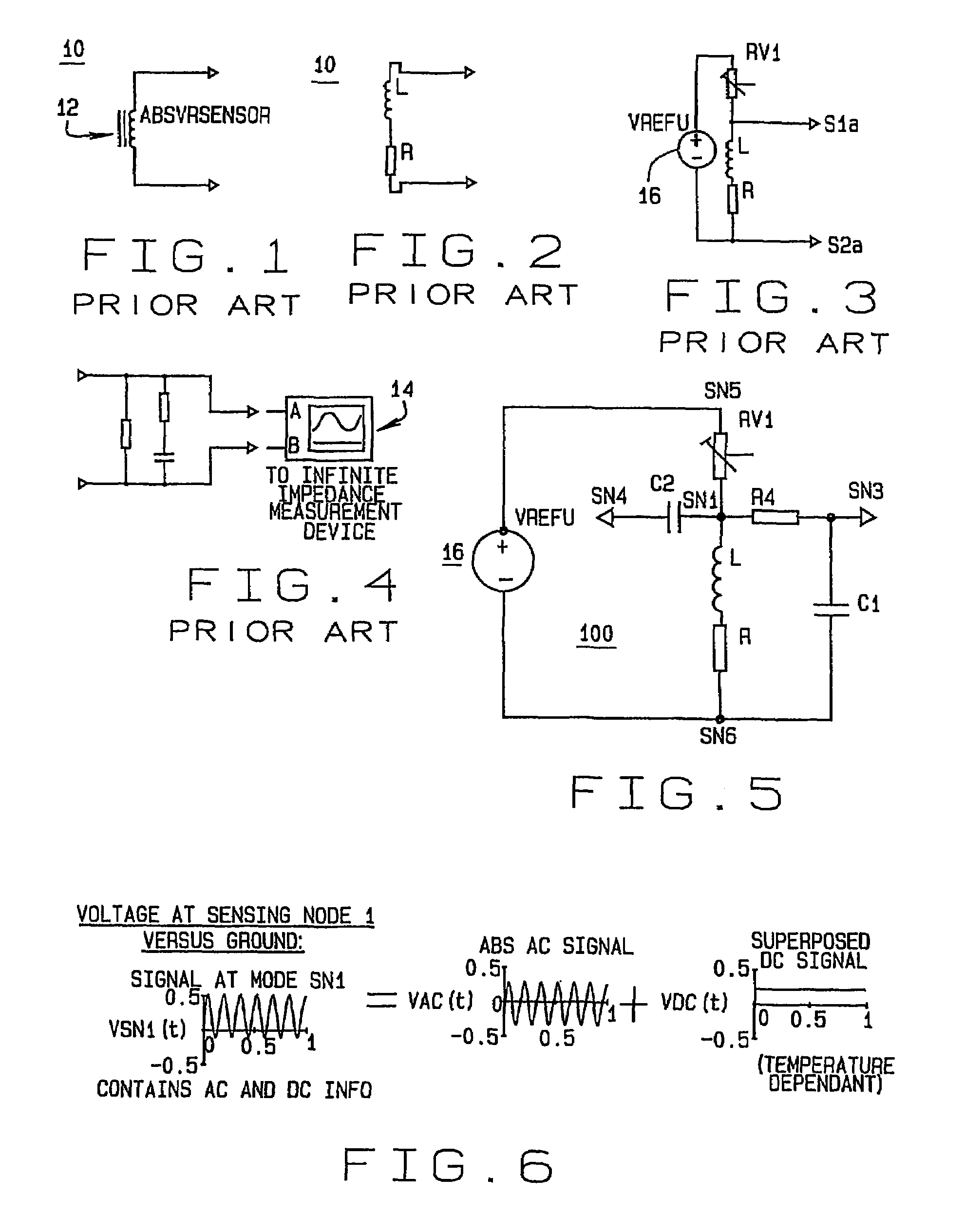
[0037]Turning to FIG. 5, in an embodiment 100 of the present invention, the voltage signals at sensing node SN1, shown in FIG. 6, represent a superposition of the DC temperature dependant signal and the AC in the coil induced voltage. To analyze and use both pieces of information, each signal is separated to provide a pure DC signal to analyze the sensor coil temperature and a pure AC signal to feed the ABS ECU. Components used to separate the superimposed AC voltage (ABS information) from the DC voltage (temperature information) at node SN1 define two filters. The first filter, consisting of resistor R4 coupled between nodes SN1 and SN3, and a capacitor C1 coupled between nodes SN3 and SN6, provides a pure DC voltage, independent from the alternating current ABS signal. The pure DC voltage signal is representative of only the temperature information.

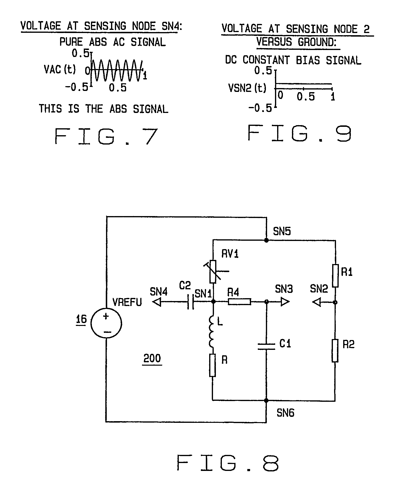
[0038]A second filter consisting of a second capacitor C2 provides a pure AC signal between nodes SN4 and SN1, as shown in FIG. 7. The...

embodiment 200

[0039]An alternate embodiment 200 of the present invention is shown in FIG. 8. A second branch with a pair of resistors R1 and R2 is added in parallel with the voltage source 16, forming a Wheatstone bridge configuration with the variable reluctance sensor (R and L) and the resistor RV1 in a first branch, and resistors R1 and R2 in a second branch. The Wheatstone bridge wiring circuit provides the ability to establish a DC bias signal, shown in FIG. 9, for the temperature information circuit. Resistors R1, R2, and RV1 can be selected to obtain a DC voltage signal of a specific value for a specific temperature of the sensor resistor R. When the circuit 200 is used to measure the temperature of a wheel bearing or other component, the bias permits the DC voltage signals to be adjusted to obtain a 0.0 mV output at a temperature of either 0° C. or 0° F. when the temperature signal is extracted between nodes SN3 and SN2, as shown in FIG. 10. Those of ordinary skill in the art will recogni...

embodiment 300

[0041]In an alternate embodiment 300, shown in FIG. 12, an additional circuit branch is inserted between SN2 and SN6. The additional circuit branch includes resistor R4BIS and capacitor C1BIS to improve signal quality at node SN2new between resistor R4BIS and capacitor C1BIS during the switch-on phase of voltage reference 16.


PUM

PropertyMeasurementUnit
ohmic resistanceaaaaaaaaaa
temperatureaaaaaaaaaa

Abstract

A temperature sensing system (100) for use with a variable reluctance sensor such as found in vehicle wheel bearing applications, which utilizes existing sensors (12) such as the antilock braking system or traction control system sensors as a direct current resistive temperature gauge. The temperature sensing system (100) includes electrical components (R4, C1) configured to separate the DC voltage (VDC(t)) representative of sensor temperature from the original magnetically induced AC voltage output signal (VSN1(t)) representative of the rotation such as vehicle wheel speed, thereby permitting the temperature sensing system (100) to be retrofitted and installed in vehicles or other components without significant alteration to an existing wiring harness or electrical components.

Description

CROSS REFERENCE TO RELATED APPLICATIONS[0001]The present application is a national stage application related to, and claiming priority from, International Application No. PCT / US03 / 032692 filed on Oct. 14, 2003, and which is herein incorporated by reference.TECHNICAL FIELD[0002]The present invention relates generally to methods and apparatus for acquiring temperature information in the proximity of a variable reluctance sensor, for example a rotation sensor associated with the bearings of a vehicle wheel, and in particular, to a method and apparatus for utilizing the properties of the variable reluctance sensor, such as a vehicle anti-lock braking system passive sensor located inside a vehicle wheel bearing, to provide a temperature dependant signal representative of the temperature at the variable reluctance sensor location.BACKGROUND ART[0003]Many automotive vehicle of current manufacture come equipped with antilock braking systems and some with traction control systems as well. In...

Claims


Application Information

Patent Timeline
Patent Type & Authority Patents(United States)
IPC IPC(8): G08B17/00G08B21/00G08B23/00H01L35/00G01K13/08
CPCG01K13/08
Inventor ADAM, CHRISTIAN
Owner THE TIMKEN CO
Why Eureka
Try Eureka