Image display apparatus

a technology of image display and display screen, which is applied in the direction of projectors, color television details, instruments, etc., can solve the problems of inability to fully express the cg contents originally possessed, and insufficient shadows and highlights, etc., to achieve reduced moiré effect, high-quality display, and reduced detail sense

Inactive Publication Date: 2009-08-18
SEIKO EPSON CORP
View PDF12 Cites 33 Cited by
  • Summary
  • Abstract
  • Description
  • Claims
  • Application Information

AI Technical Summary

Benefits of technology

[0013]It is an advantage of some aspects of the invention to provide an image display apparatus capable of preventing lowering of display image quality caused by moiré or diffraction between first and second light modulation elements and increasing luminance dynamic range and gradation number while improving display quality without raising cost.
[0016]According to an image display apparatus having a double light modulation element structure of first and second light modulation elements in related art, an optical image produced by the first light modulation element is formed on the pixel surface of the second light modulation element at the time of formation of the optical image produced by the first light modulation element via a relay optical system. In this case, moiré effect is caused by optical aberration or manufacture error of the relay lens, which lowers the image quality. According to the image display apparatus of the first aspect of the invention, the pixel surface of the second light modulation element is positioned away from the image formation surface of the optical image of the first light modulation element. Thus, the optical image of the first light modulation element is in defocus condition on the pixel surface of the second light modulation element, which prevents generation of the moiré effect. Moreover, the structure according to the first aspect of the invention can be provided only by controlling the mutual positions of the first light modulation element, the relay optical system, and the second light modulation element with no necessity for highly accurate relay lens and alignment mechanism. Thus, the cost is not raised.
[0018]When either the first light modulation element or the second light modulation element has the plural color modulation light valves which modulate a plurality of color lights having different wavelength ranges, the image display apparatus can display a color image. In this case, the color image is projected on the projection receiving surface with either the color modulation light valves or the luminance modulation light valve under the defocus condition. According to this structure, the color modulation light valve optically conjugated with the projection receiving surface is brought into focus, and the luminance modulation light valve is in defocus condition during display. This arrangement is employed based on the advantage that the color modulation light valves can modulate both luminance information and color information and thus display more image information in focus when brought into focus compared with the luminance modulation light valve which can only modulate luminance information.
[0024]According to this structure, the clearance between the pixel surface of the second light modulation element and the image formation surface of the optical image produced by the first light modulation element (D in the above equation (1)) can be increased, and therefore the defocus condition of the optical image of the first light modulation element on the pixel surface of the second light modulation element can be further widened. As a result, generation of moiré can be further reduced. Moreover, the structures of the relay lens and the alignment mechanism can be simplified, and thus cost reduction of the apparatus can be achieved.
[0026]The structure of the image display apparatus according to the second aspect of the invention can be provided by increasing the clearance between the pixel surface of the second light modulation element and the image formation surface of the optical image produced by the first light modulation element (D in the above equation (1)). Also, this structure does not have a relay optical system. Thus, the image display apparatus can reduce the moiré effect and decrease in the sense of details caused by diffraction, and provide high-quality display while achieving cost reduction of the apparatus.

Problems solved by technology

Moreover, the gradations of shadows and highlights are insufficient.
Thus, the viewers are not satisfied with the images on the display in view of reality and power of the images.
However, the ability of expression the CG contents originally posses cannot be fully offered due to insufficient performance of the display apparatus used to provide the description.
In this case, deviation or distortion of image-formation magnification is caused on the optical image of the first light modulation element due to optical aberration and manufacture error of the relay lens or for other reasons, or discrepancy of alignment between the optical image and the second light modulation element.
As a result, the grid structures of the pixels contained in the first light modulation element and the second light modulation element interfere with one another, thereby causing moiré effect and considerably deteriorating the display image quality.
For reducing generation of moiré effect, highly accurate relay lens and alignment mechanism need to be equipped, which increases the cost of the apparatus.
As a result, the projection image on the screen becomes a multiple image, which lowers the display image quality.
Moreover, fine luminance control over each pixel cannot be performed when the relay lens is eliminated, and therefore precise image expression cannot be achieved.
In this case, moiré effect is caused by optical aberration or manufacture error of the relay lens, which lowers the image quality.
However, diffraction increases when the distance between the pixel surface of the second light modulation element and the image formation surface of the optical image of the first light modulation element is excessively long.
Also, this structure does not have a relay optical system.

Method used


Image

  • Image display apparatus
  • Image display apparatus
  • Image display apparatus

Examples


first embodiment

[0037]A first embodiment of the invention is hereinafter described with referenced to FIGS. 1 through 8.

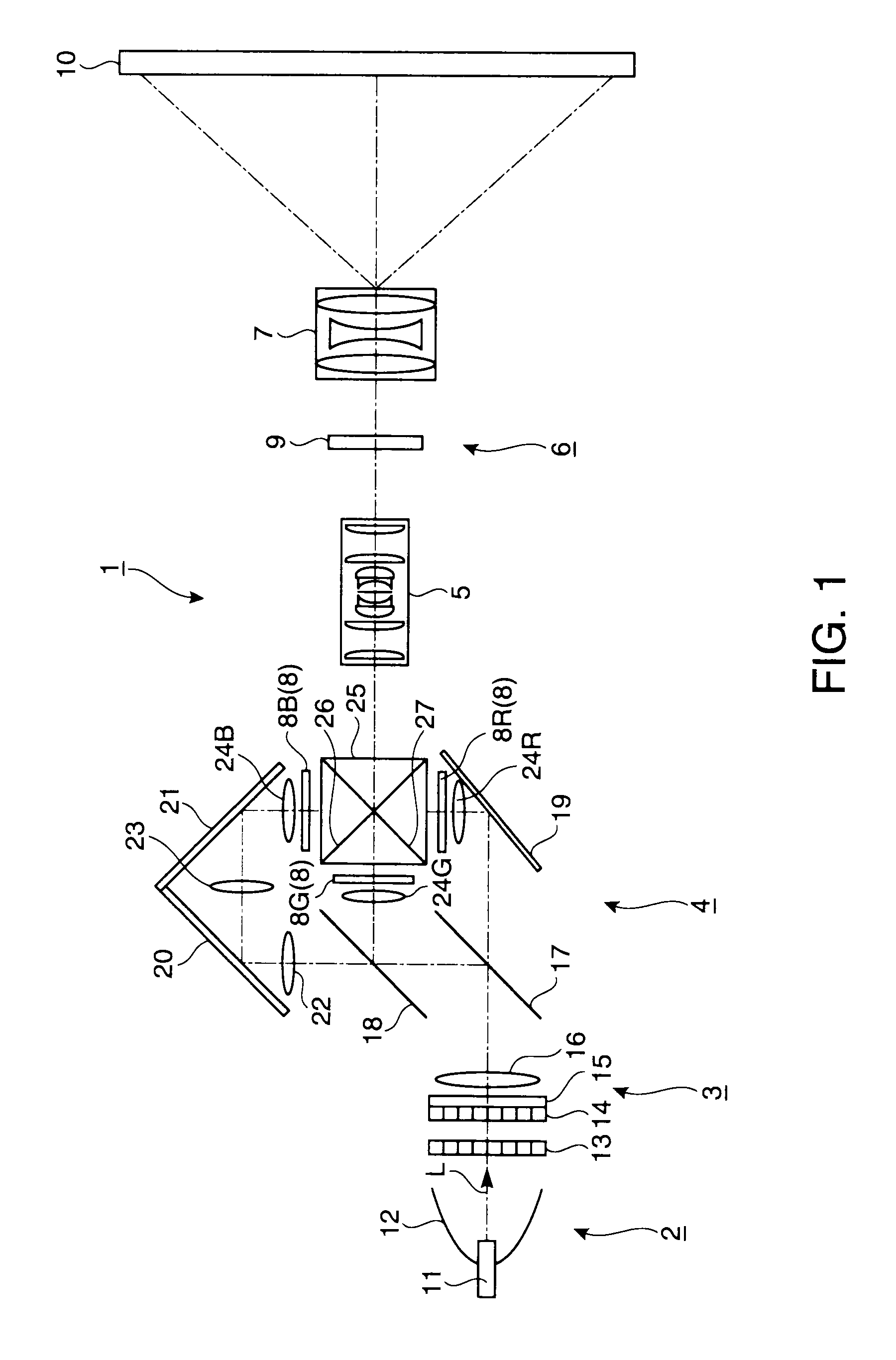
[0038]An image display apparatus according to this embodiment is an example of a double modulation system projection type image display apparatus which uses a liquid crystal light valve for both of a first light modulation element and a second light modulation element. The first light modulation element disposed near a light source (upstream side) has three transmission type liquid crystal light valves (color modulation liquid crystal light valves) for modulating different color lights of red light (R), green light (G) and blue light (B). The second light modulation element disposed far from the light source (downstream side) has one transmission type liquid crystal light valve (luminance modulation liquid crystal light valve) for modulating light produced by synthesizing the respective color lights modulated by the first light modulation element.

[0039]FIG. 1 is a view (plan view)...

second embodiment

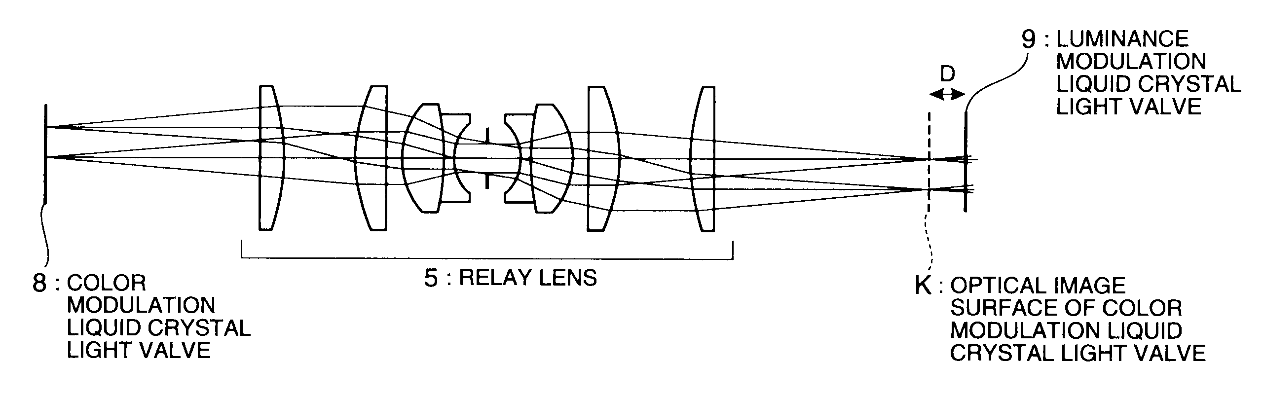
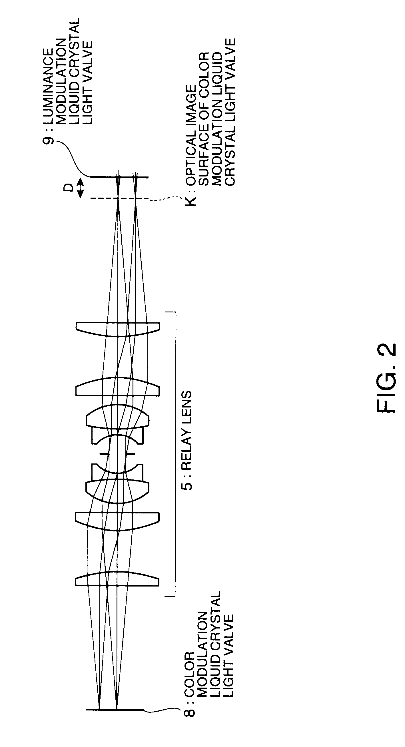
[0082]According to this embodiment, the distance D between the intermediate image surface K of the color modulation light valve 8 and the pixel surface of the luminance modulation light valve 9 is as small as 180 μm or smaller. However, this distance D can be increased by enlarging the pixel pitch p2 of the luminance modulation light valve 9 from the setting as p1=p2=10 [μm] in the first embodiment.

[0083]For example, when the pixel pitch p2 of the luminance modulation light valve 9 is increased to 30 μm with respect to the pixel pitch p1=10 μm of the color modulation light valve 8 (equal to the pixel pitch in the first embodiment), D≦818 [μm] is set for satisfying h≦1 / 2·p1 and D≦1636 [μm] is set for satisfying h≦p1. Thus, the distance D between the intermediate image surface K of the color modulation light valve 8 and the pixel surface of the luminance modulation light valve 9 can be considerably increased.

[0084]The advantage provided by increasing the distance D between the interme...

third embodiment

[0085]A third embodiment according to the invention is now described with reference to FIG. 9.

[0086]Similarly to the image display apparatus in the first embodiment, an image display apparatus according to this embodiment is a double modulation type projection image display apparatus which uses a liquid crystal light valve for both a first light modulation element and a second light modulation element. The difference in structure between the first embodiment and the third embodiment is that the relay lens for supplying the optical image of the first light modulation element to the second light modulation element is eliminated in the third embodiment.

[0087]FIG. 9 illustrates only a structure around a color modulation light valve and a luminance modulation light valve of the projection type image display apparatus according to this embodiment. In FIG. 9, the same numbers are given to the same components as those shown in FIG. 1, and detailed explanation of those components is not repe...


PUM


Abstract

An image display apparatus includes: a light source; a first light modulation element which has a plurality of pixels whose light modulation characteristics can be independently controlled and modulates light emitted from the light source; a second light modulation element which has a plurality of pixels whose light modulation characteristics can be independently controlled and modulates light emitted from the first light modulation element; and a relay optical system disposed between the first light modulation element and the second light modulation element to create an image formation surface by forming an optical image produced by the first light modulation element at a predetermined position. A pixel surface of the second light modulation element is positioned away from the image formation surface of the optical image produced by the first light modulation element.

Description

BACKGROUND[0001]1. Technical Field[0002]The present invention relates to an image display apparatus, and more particularly to an image display apparatus which includes a double light modulation element structure having a first light modulation element and a second light modulation element.[0003]2. Related Art[0004]Recently, improvement over image quality of electronic displays such as LCD (liquid crystal display), EL (electro-luminescence) display, plasma display, CRT (cathode ray tube), and projector has been remarkable, and devices having high performance substantially equivalent to vision characteristics of humans in view of resolution and color range are under development. However, according to these displays, reproducibility of the luminance dynamic range is only in the range from about 1 to about 102 [nit], and the typical gradation number is 8 bits. As for the vision of humans, however, the luminance dynamic range of recognition at a time is about 10−2 to 104 [nit], and the l...

Claims


Application Information

Patent Timeline
Patent Type & Authority Patents(United States)
IPC IPC(8): G03B21/14
CPCG03B21/00G09G3/002H04N9/3155H04N9/3126G09G2300/023G09G3/3611G03B21/005
Inventor UCHIYAMA, SHOICHI
Owner SEIKO EPSON CORP
Why Eureka
Try Eureka