Micro-mirror optical tracking and ranging system

a micro-mirror and optical tracking technology, applied in the field of optical sensing and tracking systems, to achieve the effects of high spatial resolution, physical compactness, light and inexpensive manufacturing

Inactive Publication Date: 2009-08-18
UNITED STATES OF AMERICA THE AS REPRESENTED BY THE SEC OF THE ARMY
View PDF8 Cites 46 Cited by
  • Summary
  • Abstract
  • Description
  • Claims
  • Application Information

AI Technical Summary

Benefits of technology

[0006]The invention disclosed herein incorporates state-of-the-art microelectronics, optoelectronics, and photonics technologies. One object of the invention is to detect, track, and determine object range or distance in a wide full solid-angle with an extremely high spatial resolution. Another object of the invention is to track and pin-point the range of a specific object in a very specific direction. Yet a further object of the present invention is to provide a tracking and ranging system that is physically compact, light and inexpensive to manufacture. The present invention can replace conventional radar tracking systems which lack directional precision, especially through rough terrain.

Problems solved by technology

However, all of these references pertain to display and / or projection and not detection and tracking of objects within a particular field of view.

Method used


Image

  • Micro-mirror optical tracking and ranging system
  • Micro-mirror optical tracking and ranging system
  • Micro-mirror optical tracking and ranging system

Examples


Embodiment Construction

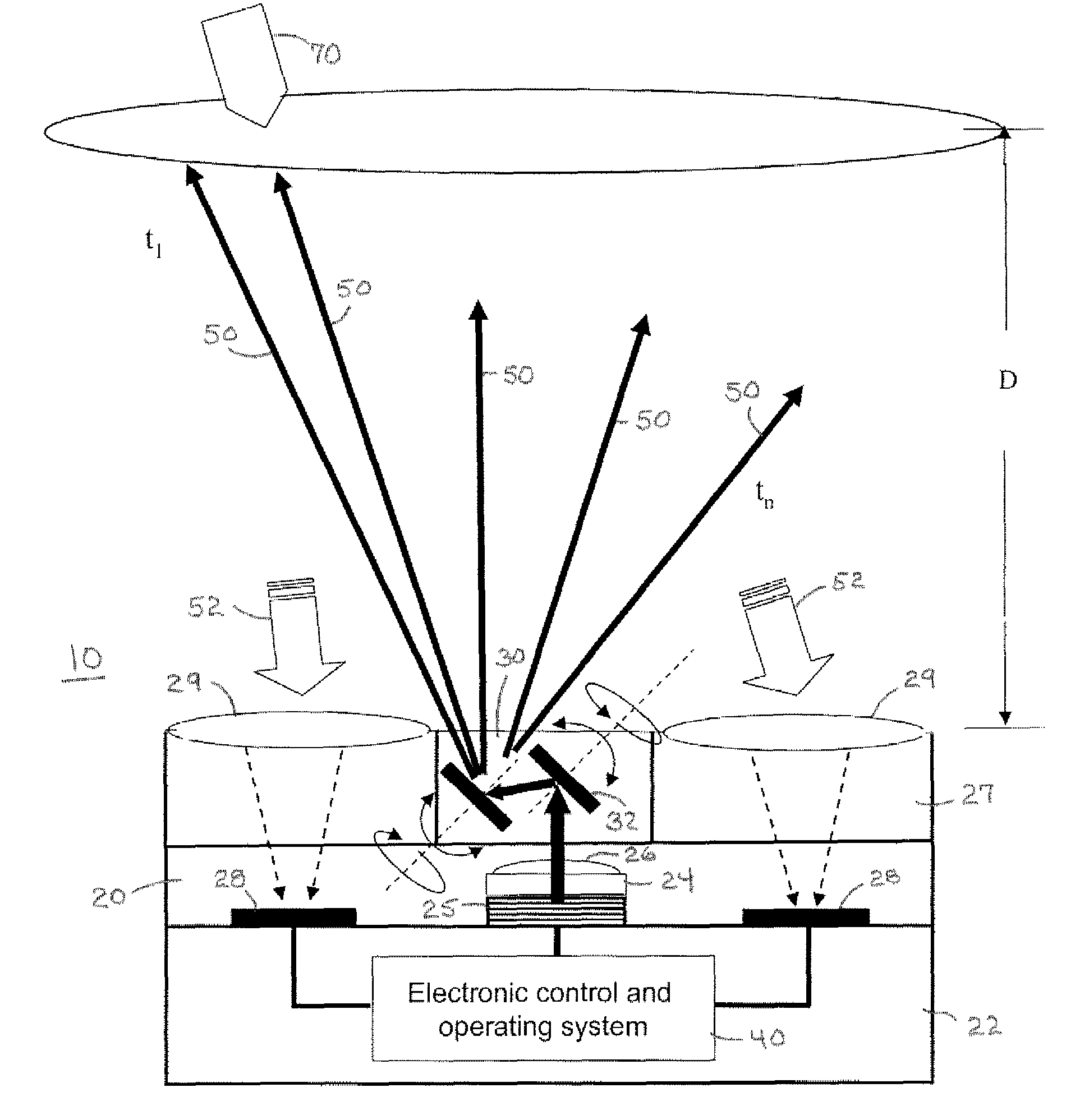
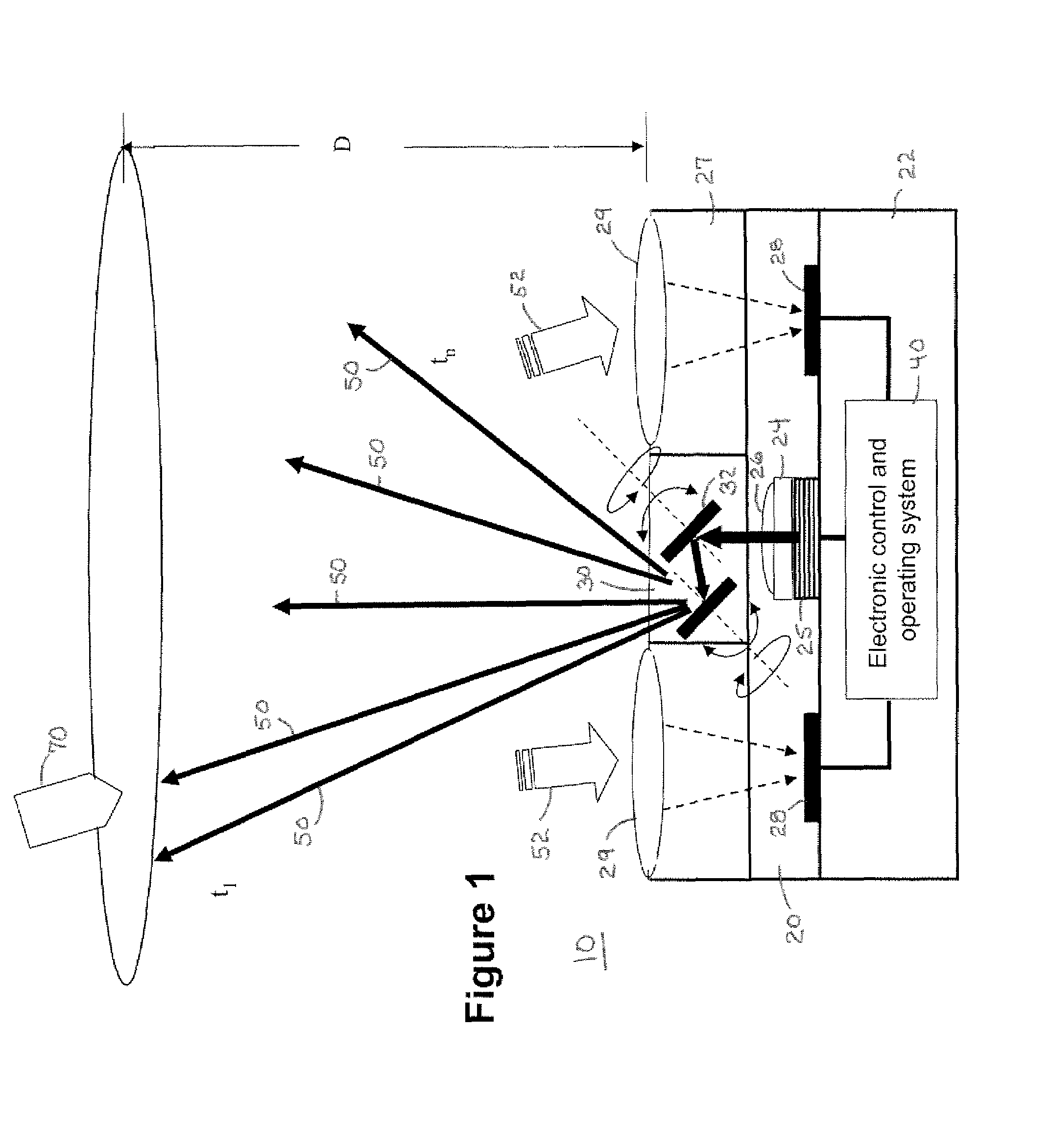
[0013]Referring now to FIG. 1, a micro-mirror optical tracking and ranging system 10 comprises an optical transceiver 20 having a Micro-Electro-Optical Mechanical System (MEOMS) micro-mirror beam steering system 30 and an electronic control and operating system 40 for processing electronic signals. The optical transceiver 20 comprises a device submount 22, a pseudo-monolithic optical laser transmitter 24 having a micro-semiconductor laser 25 and laser beam shaping and control 26, and optical photoreceiver 27 having photodetector 28 and detector focusing optic 29. The photodectors 28 can be metal-semiconductor-metal photodetectors. The MEOMS micro-mirror beam steering system 30 comprises two oppositely installed micro-mirrors 32 controlled by the electronic control and operating system 40 so that they spin and tilt synchronously and project the laser beam out in a wide solid angle. The micro-mirrors 32 are very small in mass and mounted perpendicular to the post (not shown) on which ...


PUM


Abstract

A micro-mirror optical tracking and ranging system comprises an optical transceiver having a Micro-Electro-Optical Mechanical System (MEOMS) micro-mirror beam steering system and an electronic control and operating system for processing electronic signals. An optical transceiver and MEOMS micro-mirror beam steering system comprises two oppositely installed micro-mirrors controlled so that they spin and tilt synchronously and project a laser beam out in a wide solid angle and interval in a substantially conically shaped scanning pattern. Such an optical transmitter system provides a steered frequency-modulated continuous-wave (FMCW) laser beam. When a laser beam waveform reflects off of an object within the scanned patter it is detected by the optical receiver an electronic control and operating system processes the detected laser beam waveform by mixing it with the original transmitted laser beam waveform and calculates the precise distance and location of the object.

Description

CROSS-REFERENCE TO RELATED APPLICATIONS[0001]This application claims priority of U.S. Provisional Patent Application No. 60 / 840,790 filed on Aug. 29, 2006, entitled “Micro-Mirror Optical Tracking and Ranging System.”STATEMENT REGARDING FEDERALLY SPONSORED RESEARCH or DEVELOPMENT[0002]The invention described herein may be manufactured and used by or on behalf of the Government of the United States of America for government purposes without the payment of any royalties thereon or therefore.BACKGROUND OF THE INVENTION[0003]This invention relates generally to optically sensing and tracking systems, and more particularly to an optical sensing and tracking system using a laser, micro-mirrors, microelectronics, optoelectronics and photonics technologies for detecting objects with precise range and directional resolution.[0004]An optically controlled laser transmitter and photodetector system using surface-emitting lasers and micro-optical elements, as can be used in the present invention, ...

Claims


Application Information

Patent Timeline
Patent Type & Authority Patents(United States)
IPC IPC(8): G01C3/08
CPCG01S7/4814G01S17/66G01S17/325G01S7/4817G01S17/34
Inventor LIU, JONY JIANGVON DER LIPPE, CHRISTIAN
Owner UNITED STATES OF AMERICA THE AS REPRESENTED BY THE SEC OF THE ARMY
Why Eureka
Try Eureka