Compact antenna system for polarization sensitive null steering and direction-finding

a polarization sensitive, compact technology, applied in the field of antennas, can solve the problems of partial cancellation of signal strength, signal fade or dropout, interference or jamming, etc., to enhance the tolerance of jammer to signal (j/s) of the receiver, enhance the utility and performance of the exemplary df antenna system, and mitigate the adverse impact of interference or jamming.

Active Publication Date: 2009-08-18
TOYON RES CORP
View PDF13 Cites 36 Cited by
  • Summary
  • Abstract
  • Description
  • Claims
  • Application Information

AI Technical Summary

Benefits of technology

[0015]The present invention meets some or all the needs identified above by providing a small, single aperture, low-cost controlled-receive-pattern antenna (CRPA) system for applications such as interference suppression (IS), direction-finding (DF), and threat localization. Exemplary embodiments of this invention provide an adaptive capability for mitigating the adverse impact of interference or jamming (hostile interference) to communication and navigation systems. Use may be made of a processor but interference control can be provided without multiple sets of output weights but rather by adaptively setting the biases applied to active devices in the antenna aperture. The variable impedances of these devices act in a manner that is analogous to processor weights. However, they are applied in the RF front-end where they can affect much more antenna multi-functionality than is possible with phased arrays. Moreover, like phased arrays, this system can enhance the jammer-to-signal (J / S) tolerance of the receiver and, when needed, can provide the angle-of-arrival of the interfering signal. The AOA can then be used to estimate the position of the interfering source, either through the use of several spatially diverse DF systems, or with a single DF system that is on a moving platform. A closed-loop AOA estimation process that refines the AOA estimates based on the platform dynamics can further enhance the utility and performance of the exemplary DF antenna system. The exemplary interference suppression and direction-finding system is applicable for virtually any commercial or military wireless system that is subjected to electromagnetic interference such as GPS-aided aircraft navigation systems, wireless local area networks, or wireless communications systems.

Problems solved by technology

Intentional and unintentional interference is a common problem in the field of wireless communications.
This is often referred to as multipath or coherent interference, which can lead to partial cancellation of the signal strength.
This in turn can result in signal fade or dropout.
Broadband interference is spread over a large fraction of or all of the bandwidth associated with the desired signal.
This interference looks like noise to the system and will effectively reduce the signal-to-noise ratio (SNR) and can swamp the desired signal or at least reduce its quality.
Applying narrowband-filtering or narrowband-processing techniques to the received signal can sometimes mitigate the harmful effect of narrowband interference.
In the case of digital communications, both coherent and incoherent interference can lead to unacceptable bit error rates, loss of signal lock, or a corruption of the information or message in the desired signal and hereinafter “interference” refers to both coherent and incoherent interference unless otherwise indicated.
In military systems, the loss of GPS signal lock could cause an otherwise successful mission to fail, endangering the lives of soldiers and noncombatants, and wasting valuable resources.
However, they also have drawbacks.
For some applications, the system will also require multiple AD converters.(2) The required total antenna aperture may be unacceptably large for many applications.

Method used


Image

  • Compact antenna system for polarization sensitive null steering and direction-finding
  • Compact antenna system for polarization sensitive null steering and direction-finding
  • Compact antenna system for polarization sensitive null steering and direction-finding

Examples


Embodiment Construction

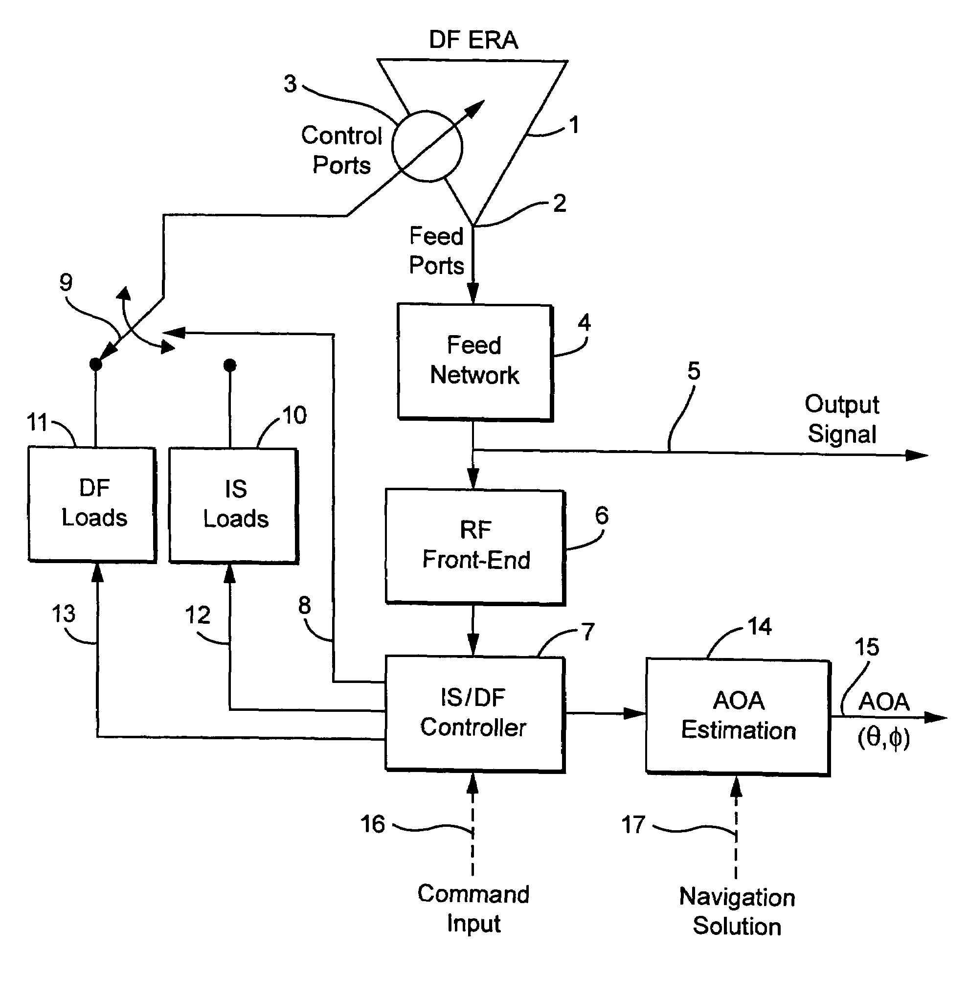
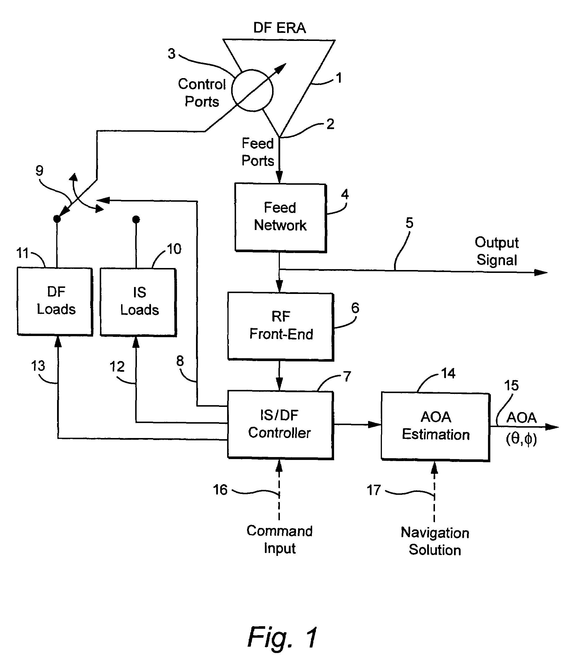
[0031]As shown in FIG. 1, in a perhaps simplest exemplary embodiment, the direction-finding and interference suppression (DF / IS) system described here may include a compact electronically reconfigurable multimode direction-finding antenna with both feed and appropriately placed control ports embedded in its aperture, a feed network, an RF front-end, microcontroller, feedback control electronics, and controllable loads attached to the control ports. While the DF capability is inherent in the choice of the multi-mode spiral antenna (Corzine et al. [1990]), the DF performance is improved through careful design of a fixed set of control loads and the optimal location of the control ports. Interference suppression is achieved through an alternative set of variable control loads that are adjusted in response to a reference signal. In spread spectrum systems this reference signal can simply be the measured power in the frequency band of interest. Alternating between the two operational mod...


PUM


Abstract

A compact, non-phased-array, electronically reconfigurable antenna (ERA) system with at least two operational modes has a first operational objective that is polarization-sensitive null steering (PSNS) and a second operational objective that is direction-finding (DF). The system can rapidly switch between two operational states. In the first state, the system behaves like a polarization filter (PF) and operates as a controlled reception pattern antenna (CRPA), while in the second state the system behaves as an angle-of-arrival (AOA) sensor and operates as a fixed reception pattern antenna (FRPA). The system may include a spiral-mode antenna with both feed and load ports; a mode-forming network; an electronics package; and feedback control electronics. Radio frequency (RF) interference rejection and RF direction-finding may be performed as well as reduction and / or elimination of multiple jamming signals that are intentionally or unintentionally directed at a Global Positioning System (GPS). The determination of direction and location of the source of jamming signals may also be achieved.

Description

RELATED APPLICATION[0001]This application is based on and claims the benefit under 35 U.S.C. §§ 119 and 120 of provisional application 60 / 580,395 filed Jun. 18, 2004.BACKGROUND OF THE INVENTION[0002]1. Field of Technology[0003]The present application relates to the field of antennas. Specifically, it relates to interference suppression (IS) and direction-finding (DF) systems.[0004]2. Related Art[0005]Intentional and unintentional interference is a common problem in the field of wireless communications. Interfering signals often share the same frequency band (or channel within the band) as the desired signal. When the desired signal arrives along a reflected path or paths it too can behave like an interference signal. This is often referred to as multipath or coherent interference, which can lead to partial cancellation of the signal strength. This in turn can result in signal fade or dropout. Signals unrelated to the desired signal are referred to as incoherent interference. Incoher...

Claims


Application Information

Patent Timeline
Patent Type & Authority Patents(United States)
IPC IPC(8): H04B1/00
CPCH01Q21/29H01Q1/243G01S3/32
Inventor EZAL, KENAN O.LARRY, THOMAS L.RICHEN, ANDREW S.WIATT, MICHAEL R.AGATE, CRAIG S.WERNER, BENJAMIN D.VANBLARICUM, MICHAEL L.
Owner TOYON RES CORP
Why Eureka
Try Eureka