Intelligent interface for controlling an adaptive antenna array

Inactive Publication Date: 2009-08-25
IPR LICENSING INC
View PDF38 Cites 27 Cited by
  • Summary
  • Abstract
  • Description
  • Claims
  • Application Information

AI Technical Summary

Benefits of technology

[0015]In contrast, existing systems typically assume the presence of a specific type of steerable antenna. Other existing techniques require the use of user-configured jumpers to enable/disable the antenna steering algorithm. The invention, instead, may provide an automated method for proper configuration of the antenna steering algorithm and elimi

Problems solved by technology

However, these mechanisms typically control only a portion of, for example, a connection of a single transceiver to one of two antenna elements.
E

Method used


Image

  • Intelligent interface for controlling an adaptive antenna array
  • Intelligent interface for controlling an adaptive antenna array
  • Intelligent interface for controlling an adaptive antenna array

Examples


Example

[0026]A description of preferred embodiments of the invention follows.

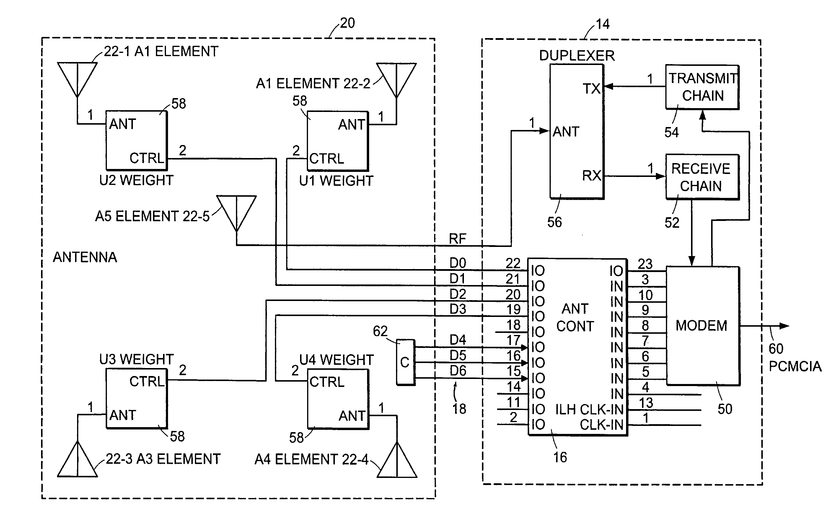
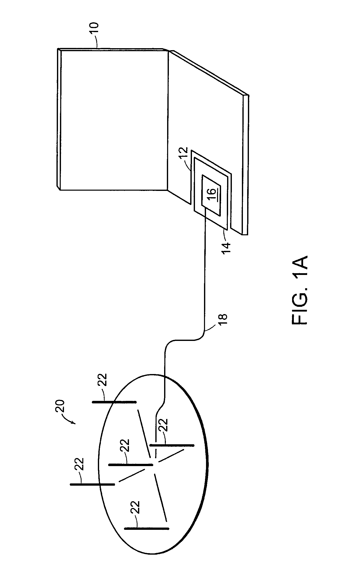
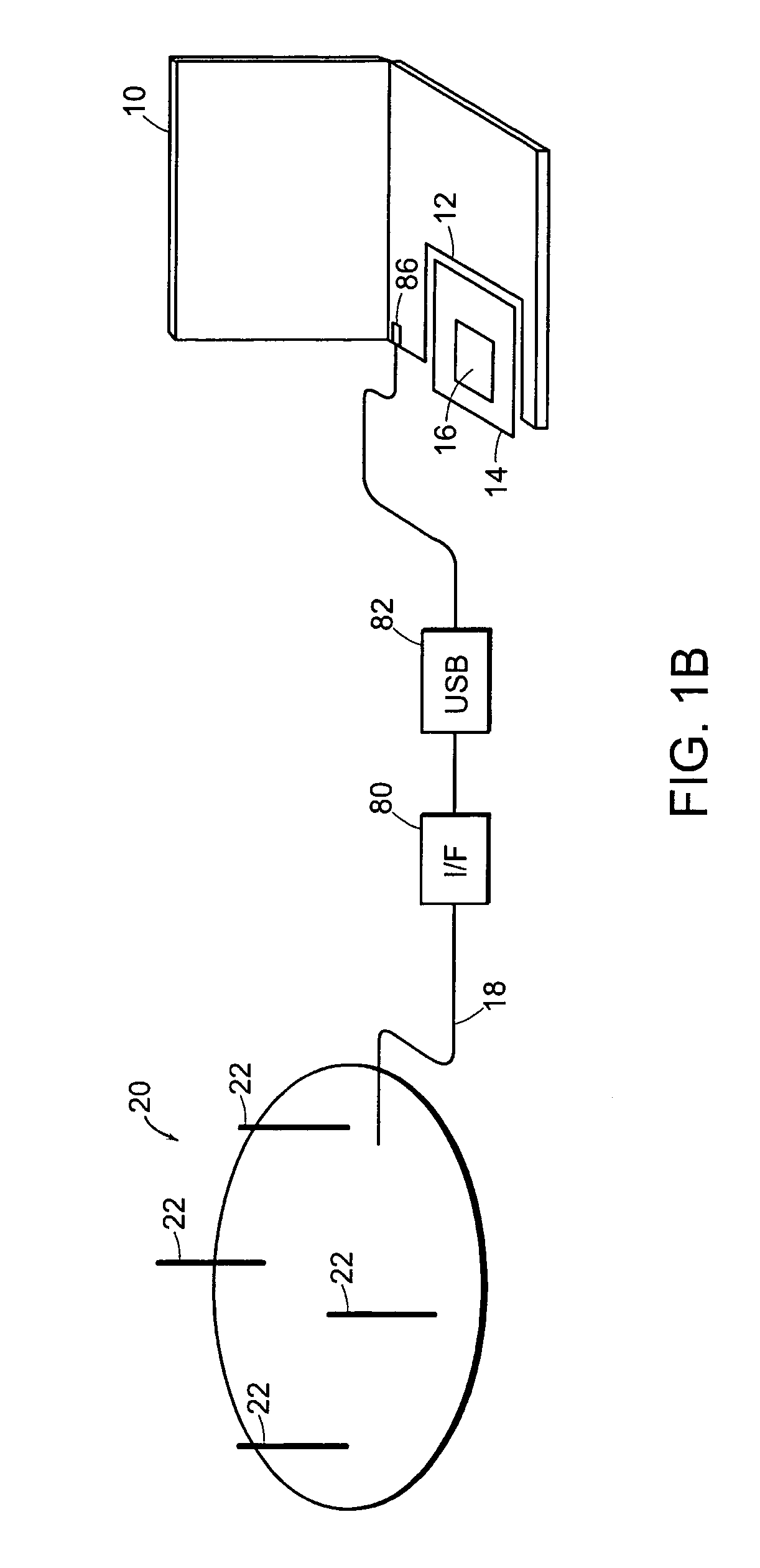
[0027]FIG. 1A illustrates an arrangement whereby a portable computing device, such as a laptop computer 10, is communicating over a wireless data network using an adaptive antenna array 20. The laptop computer 10 has, in a preferred embodiment, a standardized peripheral slot 12, such as a Personal Computer Memory Card International Association (PCMCIA) compatible slot 12. The PCMCIA slot 12 has within it a PCMCIA modem card 14. The modem card 14, as will be understood in more detail shortly, includes (i) wireless data modem circuitry, (ii) an antenna control interface 16 for setting parameters for the controllable antenna array 20, as well as (iii) radio transmitter and receiver equipment. Of specific interest is the antenna control interface 16, which may be used to generate control signals that are used to control the parameters of the array 20. Such control signals, as well as radio frequency signals, pass betw...


PUM


Abstract

An antenna control interface is integrated with common integrated circuit components, such as radio transceiver or baseband modem signal processing control logic. The antenna control interface controls the operation of an adaptive antenna array used with wireless communication system devices.

Description

[0001]This application claims priority to prior U.S. Provisional Patent Application Ser. No. 60 / 361,418 filed Mar. 1, 2002 entitled “ASIC Interface for Controlling Adaptive Antenna Array” and prior U.S. Provisional Patent Application Ser. No. 60 / 415,265 filed Sep. 30, 2002 entitled “Intelligent Interface for Controlling an Adaptive Antenna Array.” The entire teachings of both prior provisional applications are hereby incorporated by reference.BACKGROUND OF THE INVENTION[0002]The present invention is related to antenna systems for use with wireless radio modems that may be used to provide a communication link for mobile computers.[0003]The demand for use of data processing equipment continues to increase, including demand for not only desktop personal computers but also portable laptop computer and Personal Digital Assistant (PDA) devices. One undeniable trend in the proliferation of small data processing devices is the need to interconnect them—and the public increasingly desires to...

Claims


Application Information

Patent Timeline
IPC IPC(8): H04B7/14G01S5/04H01Q3/00H01Q3/02H01Q3/12H04M1/00H04B7/212H03F3/16H04B1/00H04B1/06H04B1/38H04B15/00H04B7/00H01Q3/44H01Q1/22H01Q1/24H01Q3/26H01Q19/32H04B7/26
CPCH01Q1/22H01Q1/2258H01Q19/32H01Q1/242H01Q3/2605H01Q1/2275H01Q21/00
Inventor GORSUCH, THOMAS E.REGNIER, JOHN A.HOFFMANN, JOHN E.NELSON, JR., GEORGE RODNEYPROCTOR, JR., JAMES A.
Owner IPR LICENSING INC
Why Eureka
Try Eureka