Hybrid plasma-cold spray method and apparatus

a plasma-cold spray and hybrid technology, applied in plasma welding apparatus, plasma technique, manufacturing tools, etc., can solve the problems of tensile stress as the coating cools and contracts, cracking of the coating, and the velocity in these designs has been limited to approximately mach 1 in standard operating environments, so as to improve the process efficiency and reduce the gas consumption. , the effect of widening the operating range of particle velocity

Active Publication Date: 2009-09-01
SULZER METCO (US) INC
View PDF10 Cites 32 Cited by
  • Summary
  • Abstract
  • Description
  • Claims
  • Application Information

AI Technical Summary

Benefits of technology

[0012]The present invention provides a method and apparatus of producing a dense coating with desirable stress conditions similar to coatings produced by a cold spray processes, but with higher process efficiencies and lower gas consumption. The inventive process combines features of a plasma process method of gas heating and a cold spray process to accelerate the gas. The deposition process does not melt the material feedstock particles in the effluent stream, but uses a convergent / divergent nozzle to accelerate the heated gas to supersonic speed. Material feed injection is accomplished past the divergent section of the nozzle in to the supersonic gas flow. As a result, the present invention provides a more efficient mechanism for producing coatings with the desirable features of a cold-spray coating, but with the potential for a wider operating range of particle velocities and temperatures not available to conventional plasma or cold-spray deposition techniques.

Problems solved by technology

Classic thermal spray processes that produce coating as a result of melting or partial melting of the feedstock material result in tensile stresses as the coating cools and contracts.
These tensile stresses often result in cracking of the coating, especially when producing thick layers or combining different layers of dissimilar materials.
But the velocity in these designs has been limited to approximately Mach 1 in standard operating environments.
In these previous cases the gas / particle temperatures were too high and often well in excess of the material melting temp.
In addition, with the plasma process and even the high velocity oxygen fuel (HVOF) and cold spray processes, the operating efficiency and expected hardware life decreased rapidly as gas velocities increased.
Also, as gas flows and pressures are increased in a conventional plasma gun, the stability of the arc decreased and the arcs become more constricted.

Method used


Image

  • Hybrid plasma-cold spray method and apparatus
  • Hybrid plasma-cold spray method and apparatus
  • Hybrid plasma-cold spray method and apparatus

Examples


Embodiment Construction

[0022]Reference will now be made in detail to the preferred embodiments of the present invention, examples of which are illustrated in the accompanying drawings.

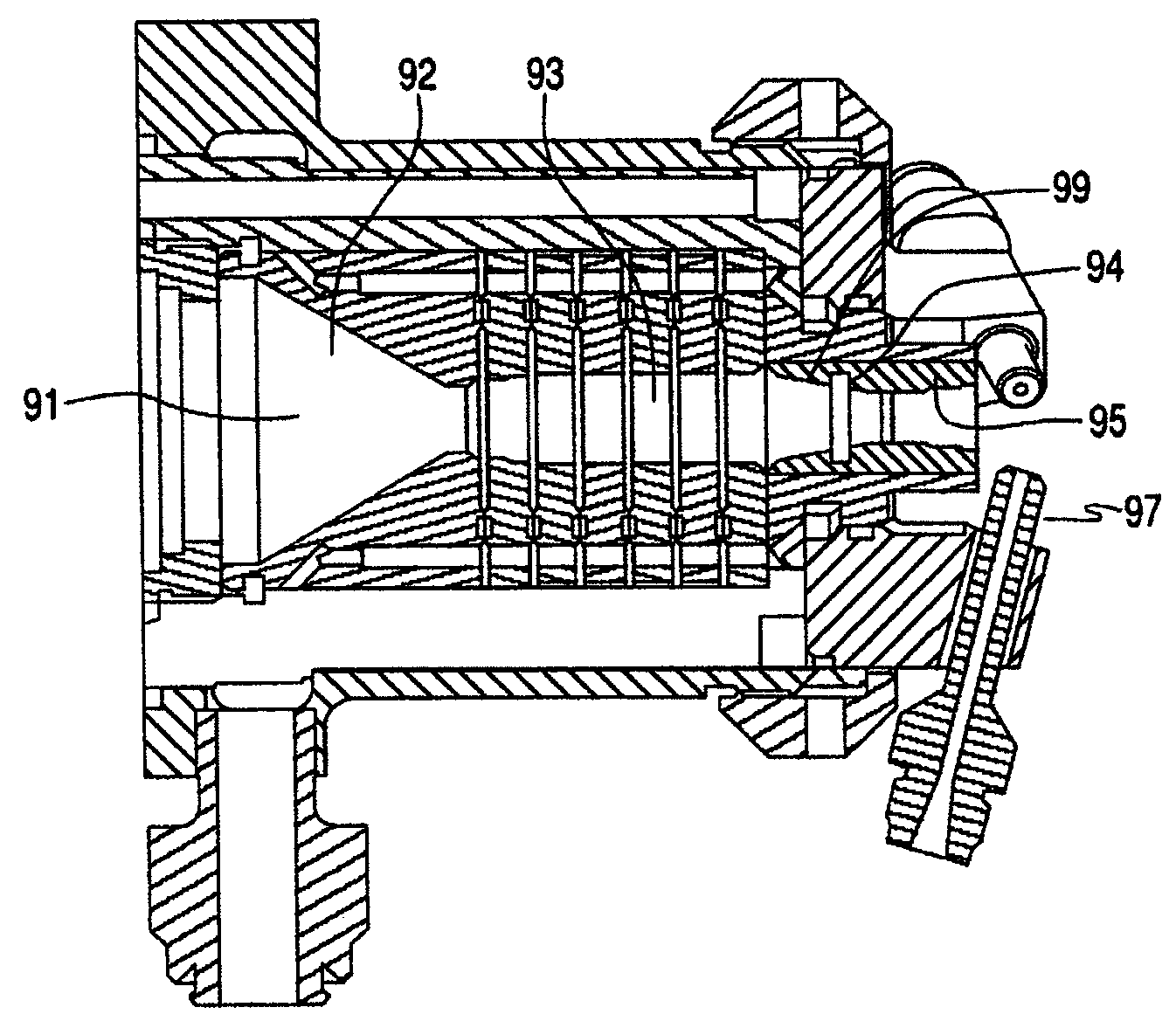
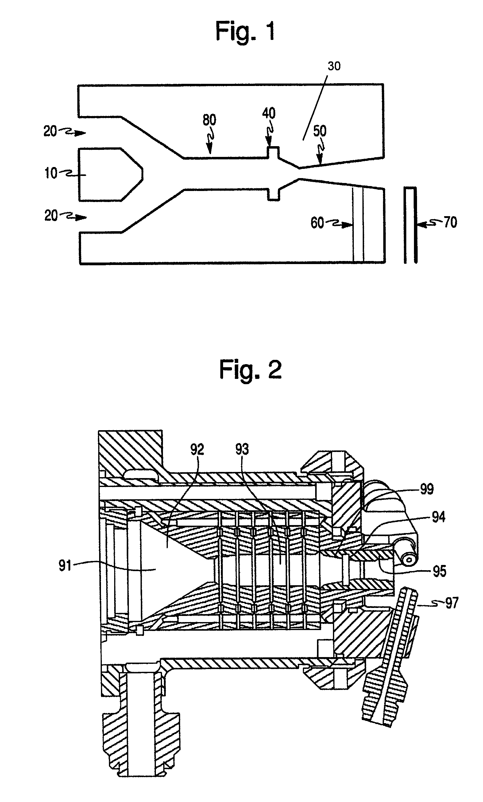
[0023]FIG. 1 depicts one embodiment of a hybrid gun in accordance with the present invention. While the hybrid gun of FIG. 1 is described in terms of retrofit of an existing plasma gun, the described features are also contemplated for use as original factory equipment. In the figure, an electrode 10 remains typical of a plasma gun along with a gas injection inlet(s) 20 at the rear of the gun. A nozzle 30 is elongated to include a step 40 and a convergent / divergent section 50. The convergent / divergent supersonic nozzle section 50 can also be electrically isolated from the anode section 80 of the nozzle 30 to assist in preventing the arc from entering the supersonic nozzle section 50. Suitable material construction of the nozzle bore walls to withstand both heat and abrasion is required for hardware life. For example, material...


PUM

PropertyMeasurementUnit
particle velocitiesaaaaaaaaaa
voltage potentialaaaaaaaaaa

Abstract

The present invention provides a method and apparatus of producing a dense coating with desirable stress conditions similar to coatings produced by a cold spray processes, but with higher process efficiencies and lower gas consumption. The inventive process combines features of a plasma process method of gas heating and a cold spray process to accelerate the gas, incorporating these elements into a single hybrid process.

Description

CROSS REFERENCE TO RELATED APPLICATIONS[0001]This application claims priority under 35 U.S.C. § 119(e) from U.S. Provisional Patent Application No. 60 / 752,061, filed on Dec. 21, 2005, which is incorporated herein in its entirety by reference.STATEMENT REGARDING SPONSORED RESEARCH OR DEVELOPMENT[0002]Not ApplicableREFERENCE TO SEQUENCE LISTING[0003]Not ApplicableBACKGROUND OF THE INVENTION[0004]1. Field of the Invention[0005]The present invention relates to a method and apparatus for producing coatings using supersonic gas flow. More specifically, the present invention relates to a method and apparatus that applies coatings using a hybrid of plasma and cold-spray coating techniques.[0006]2. Description of Related Art[0007]Plasma thermal spray processes have been used in the coatings industry for many years. The plasma thermal spray process basically involves spraying molten or heat softened material onto a substrate to form a coating. Feedstock material, typically in powder form, is ...

Claims


Application Information

Patent Timeline
Patent Type & Authority Patents(United States)
IPC IPC(8): B23K10/00
CPCB23K10/027C23C4/12C23C24/04H05H1/42H05H1/34H05H2001/3484H05H2001/3452H05H1/3452H05H1/3484C23C4/00
Inventor MOLZ, RONALD J.HAWLEY, DAVIDMCCULLOUGH, RICHARD
Owner SULZER METCO (US) INC
Why Eureka
Try Eureka