
High-speed measuring device and method based on a confocal microscopy principle

a high-speed measuring and confocal microscopy technology, applied in the field of scanning system and method based on the principle of confocal microscopy, can solve the problems of wasting time, wasting time, and wasting time, and achieve the effect of simple correlation and altered sensitivity of sensor elements

Active Publication Date: 2009-09-01
SIRONA DENTAL SYSTEMS
View PDF7 Cites 57 Cited by
  • Summary
  • Abstract
  • Description
  • Claims
  • Application Information

AI Technical Summary

Benefits of technology

The invention is a scanning system based on confocal microscopy that uses a light source, imaging optics, and an image detector to measure objects. The system has several advantages, including the ability to measure multiple points on the object simultaneously, the use of an aperture array for two-dimensional scanning, and the use of a line sensor for three-dimensional imaging. The system can also use a beam splitter to improve the signal-to-noise ratio and calibration. The invention allows for faster and more accurate measurements using confocal microscopy.

Problems solved by technology

However, typically frame sequences of some 10 to 100 frames must be recorded, so that the measuring procedure, using current recording technologies, takes several seconds or even longer.

Method used


Image

  • High-speed measuring device and method based on a confocal microscopy principle
  • High-speed measuring device and method based on a confocal microscopy principle
  • High-speed measuring device and method based on a confocal microscopy principle

Examples


Embodiment Construction

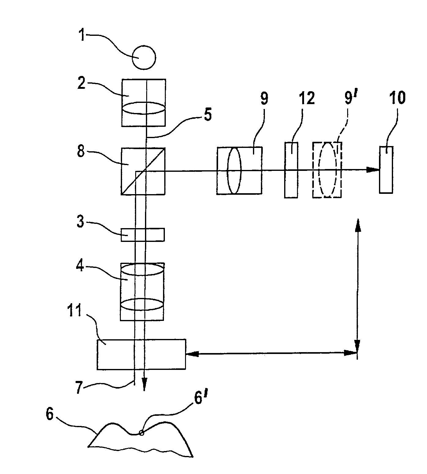
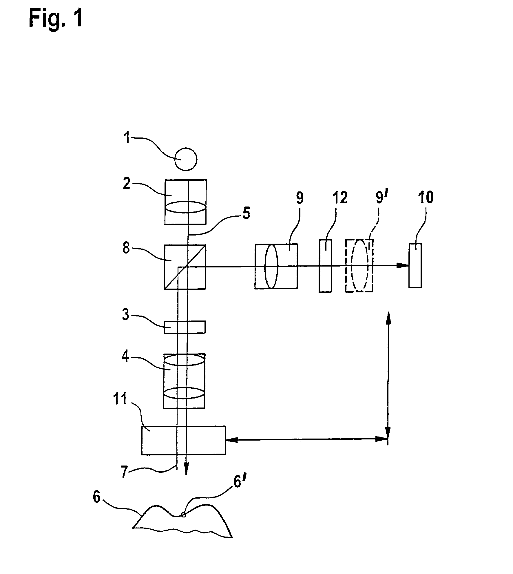
[0043]FIG. 1 shows a basic structure of the scanning device according to the basic principle of confocal microscopy. The scanning device comprises a light source 1, which typically emits monochromatic or white light.

[0044]The light source 1 is reproduced in a suitable way on an aperture array 3 using optics 2. The aperture array 3 can be in the form of a drilled board. In the case of more developed applications, an arrangement of micro-lenses can be used, if desired. This arrangement can be moved rapidly, if appropriate, for the full-area scanning of the object, in which case an image must be created in each position.

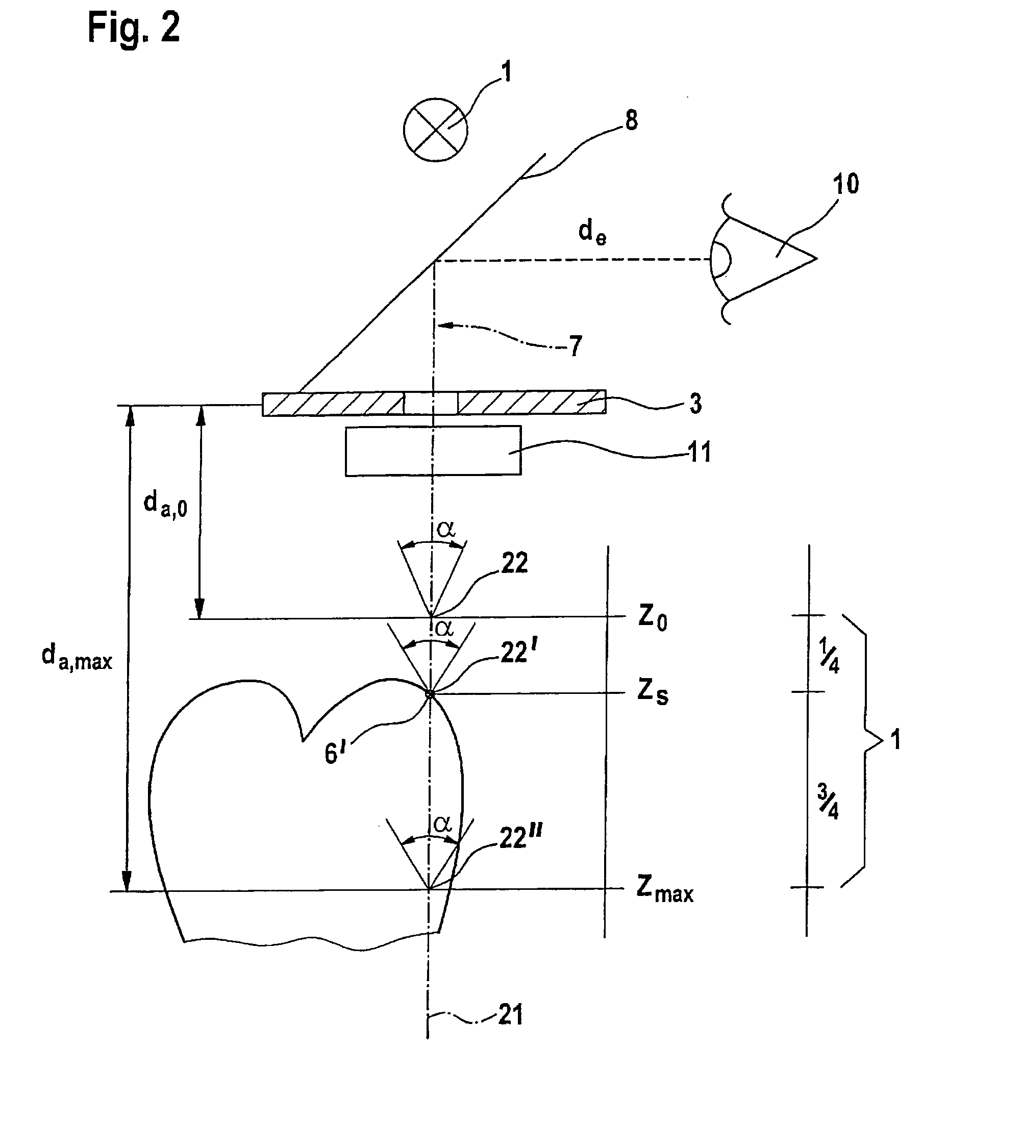
[0045]By means of imaging optics 4, which are usually designed telecentrically, the light emitted from the aperture array 3 is reproduced on an object 6 to be scanned. The optical distance of the imaging optics 4 relative to the object 6 can be changed so that different altitude lines of the object to be scanned are located in the image plane of the imaging optics. The ...


PUM


Abstract

The invention relates to a measuring device and a method based on a confocal microscopy principle. The inventive device comprises a light source (1), a diaphragm unit (3) for limiting a beam, an imagine optical system (4) for focusing the light (5) which is irradiated by said source on a measurable object (6) and passes through said diaphragm unit. Said device also comprises an optical system (10) for receiving the light (5) reflected from the object and passing through said optical system or another diaphragm unit disposed in an observation beam (7) and an image receiver (10) which is provided with at least two radiation-sensitive sensor elements (13, 14) (pixel). Said invention is characterized in that, in order to obtain the image of an altitude information-containing measurement, the device is also provided with means (11) for modifying the beam optical path length disposed between the light source (1) and / or the image receiver (10), on one side, and the object (6) on the other and the optical distance (d) of a focal point is modifiable in a predetermined manner. In addition, said intention makes it possible to influence the dependence of an accumulation of charges (Q13, Q14) in at least two sensor elements (13, 14) on the light intensity of the observation beam (7) during the exposure time in such a way that a correlation associated with the optical distance (d) of an image plane can be carried out by the imagine optical system (4), thereby making it possible to reconstitute the altitude co-ordinate (zs) of the object by distributing the intensity values obtained during the exposure time from at least two sensor elements (13, 14).

Description

BACKGROUND OF THE INVENTION[0001]1. Field of the Invention[0002]The invention relates to a scanning system and method based on the principle of confocal microscopy.[0003]2. The Prior Art[0004]Such scanning systems are used for scanning an object and for enabling both scanning of a point along an axis (two-dimensional scanning) and scanning of a surface disposed about an axis (three-dimensional scanning). Thus, such a device is suitable for a point sensor and a flat panel sensor.[0005]The basic principles of confocal 3D scanning are known. The determination of the altitude of a point on an object is achieved in the prior art by determining, for each point of a drilled board constituting an aperture array, that position of the object, relative to the imaging optics or the entire scanning device, at which the greatest amount of light travels back through the drilled board. In addition, during the movement of the object relative to the imaging optics, a plurality of image frames is reco...

Claims


Application Information

Patent Timeline
Patent Type & Authority Patents(United States)
IPC IPC(8): G02B7/04G01B11/24G02B21/00
CPCA61C9/0066G02B21/0084G02B21/006G01B11/0608
Inventor PFEIFFER, JOACHIM
Owner SIRONA DENTAL SYSTEMS
Learn More