Compressor bearing and compressor component

a compressor and bearing technology, applied in the direction of positive displacement liquid engines, piston pumps, liquid fuel engines, etc., can solve the problems of difficult to achieve the number of grains exceeding 13 and achieve the effect of high anti-crack strength, long fatigue life and high strength

Inactive Publication Date: 2009-09-08
NTN CORP
View PDF38 Cites 6 Cited by
  • Summary
  • Abstract
  • Description
  • Claims
  • Application Information

AI Technical Summary

Benefits of technology

[0013]The present invention aims to provide a compressor bearing and a compressor component with a high strength and having (1) a long fatigue life (a long rolling fatigue life in a compressor bearing), (2) a high anti-crack strength, and (3) dimensional stability enhanced by restraining an increase in secular dimensional variation rate.

Problems solved by technology

Although further finer austenite grains are desirable, the grain size number exceeding 13 is usually difficult to achieve.

Method used


Image

  • Compressor bearing and compressor component
  • Compressor bearing and compressor component
  • Compressor bearing and compressor component

Examples


example 1

[0105]JIS-SUJ2 (1.0 wt % of C—0.25 wt % of Si—0.4 wt % of Mn—1.5 wt % of Cr) was used for Example 1 of the present invention. Samples shown in Table 1 were each produced through the procedure described below.

[0106]

TABLE 1SamplesConventionallyNormallycarbonitridedquenchedABCDEFproductproductSecondary7801)800815830850870——quenchingtemp. (° C.)Hydrogen—0.370.400.380.420.400.720.38content(ppm)Grain size No.—1211.51110101010(JIS)Charpy impact—6.656.406.306.206.305.336.70value (J / cm2)Fracture stress—2840278026502650270023302770value (MPa)Rolling contact—5.44.23.52.92.83.11fatigue liferatio (L10)1)Not evaluated this time due to insufficient quenching.

Samples A-D

Examples of the Present Invention

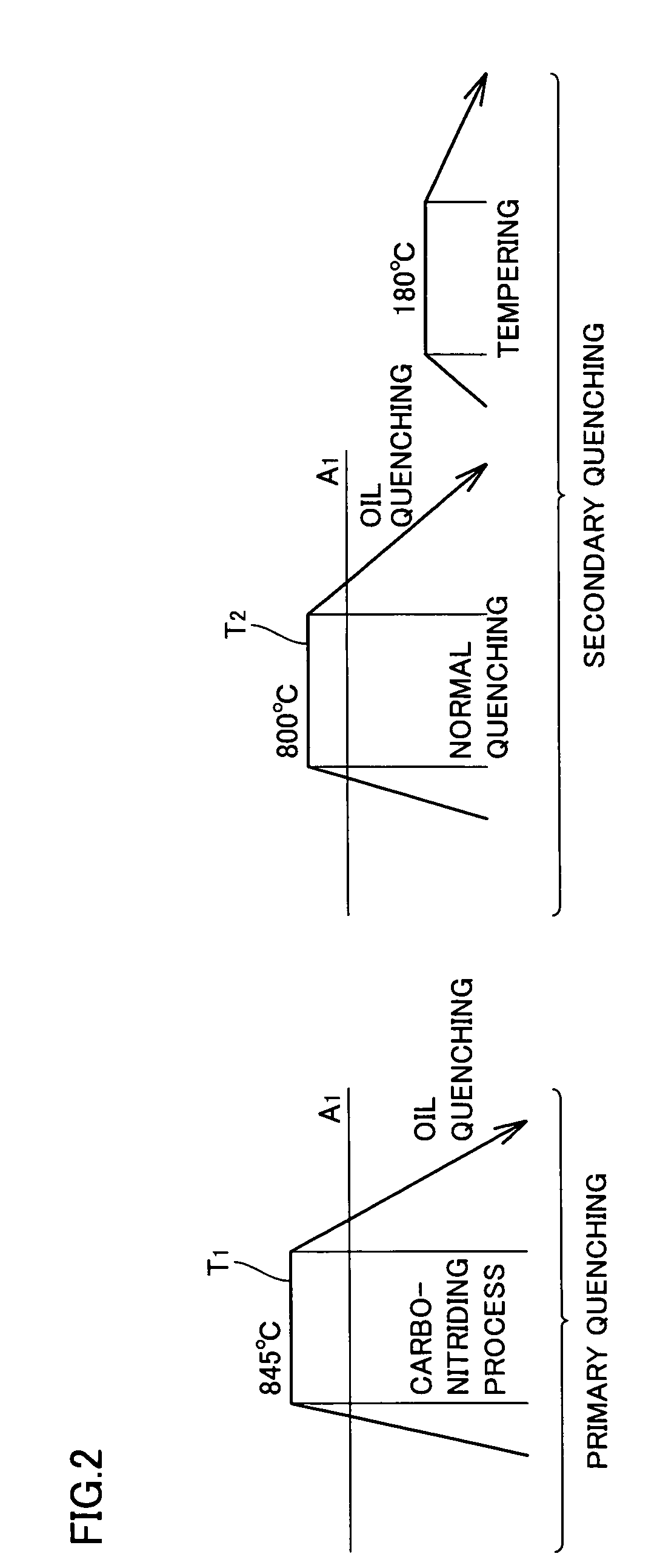
[0107]Carbonitriding was performed at 850° C. held for 150 minutes in an atmosphere of a mixture of RX gas and ammonia gas. Following the heat treatment pattern shown in FIG. 2, primary quenching was done from a carbonitriding temperature of 850° C., and secondary quenching was subsequently done by h...

example 2

[0153]Example 2 of the present invention is now described.

[0154]On the following samples X, Y and Z, a series of tests was conducted. A material to be heat-treated that was employed commonly to samples Y-Z was JIS-SUJ2 (1.0 wt % of C—0.25 wt % of Si—0.4 wt % of Mn—1.5 wt % of Cr). Samples X-Z were each processed through the following procedure.

[0155]Sample X—comparative example: normal quenching only (without carbonitriding)

[0156]Sample Y—comparative example: quenching directly after carbonitriding (conventional carbonitriding and quenching)

Carbonitriding was conducted at 845° C. held for 150 minutes. The atmosphere in the carbonitriding process was a mixture of RX gas and ammonia gas.

[0157]Sample Z—example of the present invention: A bearing material was processed following the heat treatment pattern shown in FIG. 2. Carbonitriding was conducted at 845° C. held for 150 minutes. The atmosphere in the carbonitriding process was a mixture of RX gas and ammonia gas. Final quenching tem...


PUM

PropertyMeasurementUnit
temperatureaaaaaaaaaa
grain sizeaaaaaaaaaa
grain diameteraaaaaaaaaa

Abstract

A compressor component incorporated into a compressor having a compressor body and a compressor pulley mechanism transmitting a driving force to the compressor body has an austenite grain with a grain size number falling within a range exceeding 10, a fracture stress value of at least 2650 MPa, or a hydrogen content of at most 0.5 ppm. This provides a compressor component and a compressor bearing with a long fatigue life, a high anti-crack strength, and a reduced secular dimensional variation.

Description

BACKGROUND OF THE INVENTION[0001]1. Field of the Invention[0002]The present invention relates to a compressor bearing used for a compressor body and a pulley mechanism transmitting a driving force to the compressor body, and a compressor component.[0003]2. Description of the Background Art[0004]To increase the life of a rolling bearing incorporated into a compressor with a pulley mechanism (referred to as a compressor bearing hereinafter), a thermal treatment is performed. Conventionally, for example, in quenching the components they are heated in an ambient RX gas with ammonium gas further introduced therein to carbo-nitride their surface layer portion. This carbonitriding process can harden the surface layer portion and generate retained austenite in a microstructure to provide increased rolling contact fatigue life (Japanese Patent Laying-Open Nos. 11-101247 and 8-4774).[0005]The above-mentioned carbonitriding process for the compressor bearing components is a process to diffuse ...

Claims


Application Information

Patent Timeline
Patent Type & Authority Patents(United States)
IPC IPC(8): F16C33/62F04B39/00F04B27/08F04B27/10F04C18/02F04C29/00F16C33/34
CPCC22C38/02C22C38/04C22C38/18F04B27/0873F04B27/0895F04B27/1063F04C29/005F16C33/547F16C33/56F04B39/12F04C18/0207F05C2251/02F04C2240/50F05C2201/0433F16C33/62F16C2204/62F16C2240/06F16C2360/00F16C2361/63
Inventor OHKI, CHIKARAGOTO, TOMOAKI
Owner NTN CORP
Why Eureka
Try Eureka