
Electronic endoscope, and method for transferring programs

a technology of electronic endoscope and program transfer, which is applied in the field of electronic endoscope system, can solve the problems of difficult to guarantee the transfer rate is relatively low, and the safety of the processor is not guaranteed, and achieves the effect of high speed

Inactive Publication Date: 2009-09-08
FUJI PHOTO OPTICAL CO LTD
View PDF9 Cites 2 Cited by
  • Summary
  • Abstract
  • Description
  • Claims
  • Application Information

AI Technical Summary

Benefits of technology

Enables rapid and safe firmware updates for electronic endoscopes, reducing examination delays and eliminating the need for external power sources or complex cabling, while ensuring electrical safety by maintaining insulation between circuits.

Problems solved by technology

However, once a processor cover is opened, it may become difficult to guarantee safety of the processor because of possible electrical leaks or other problem, giving rise to a necessity for re-verification of the processor.
Generally, safety of a processor is not guaranteed once a screw of a processor cover is removed.
However, generally speaking, a transfer rate is relatively low in the case of a serial transfer by way of RS-232 interface.
That is to say, there is a problem that a transfer of an update program by way of RS-232 interface takes considerably a long time.
A long transfer time of an updated program could result in a detrimentally long delay of an endoscopic examination.
If transfer of an updated program take a long time, a patient has to wait for a long time before taking an examination by a new scope.
Besides, in a case where a notebook PC is connected to a processor for updating a firmware to a new version, the use of a non-medical notebook PC in a medical environment can give rise to other problems.
In such a case, if it takes an unduly long time in acquiring an updating program at the secondary circuit by serial transfer prior to transfer to the patient's circuit and the scope connector, the serial transfer becomes a bottle neck requiring an extremely long time for updating the version of the firmware ROM in the patient's circuit as well as the firmware ROM in the scope connector.
In addition, it is impractical to use USB because it requires an immense memory space due to a large overhead.

Method used


Image

  • Electronic endoscope, and method for transferring programs
  • Electronic endoscope, and method for transferring programs
  • Electronic endoscope, and method for transferring programs

Examples


Embodiment Construction

A. Configuration of Electronic Endoscope System According to the Invention:

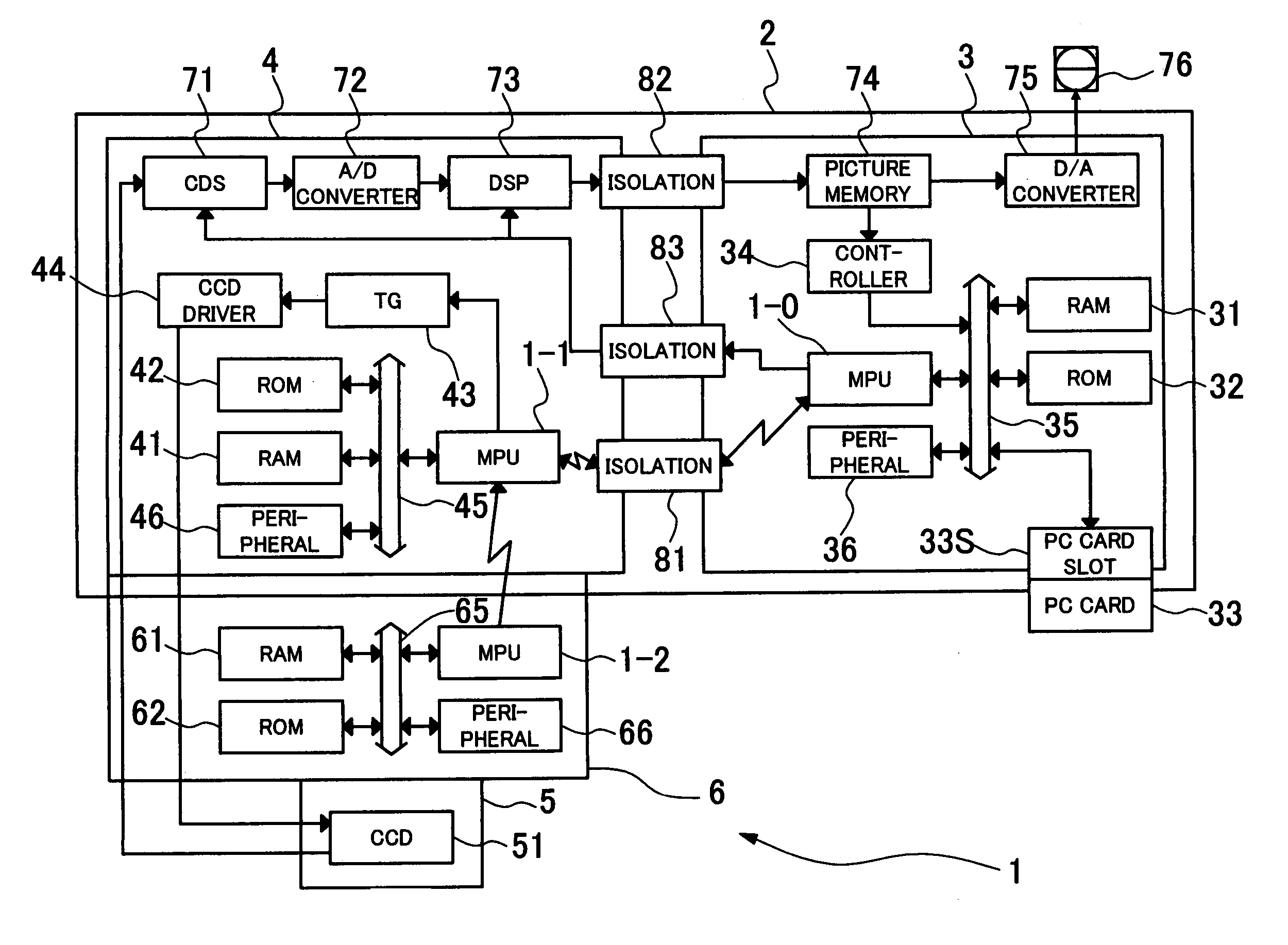
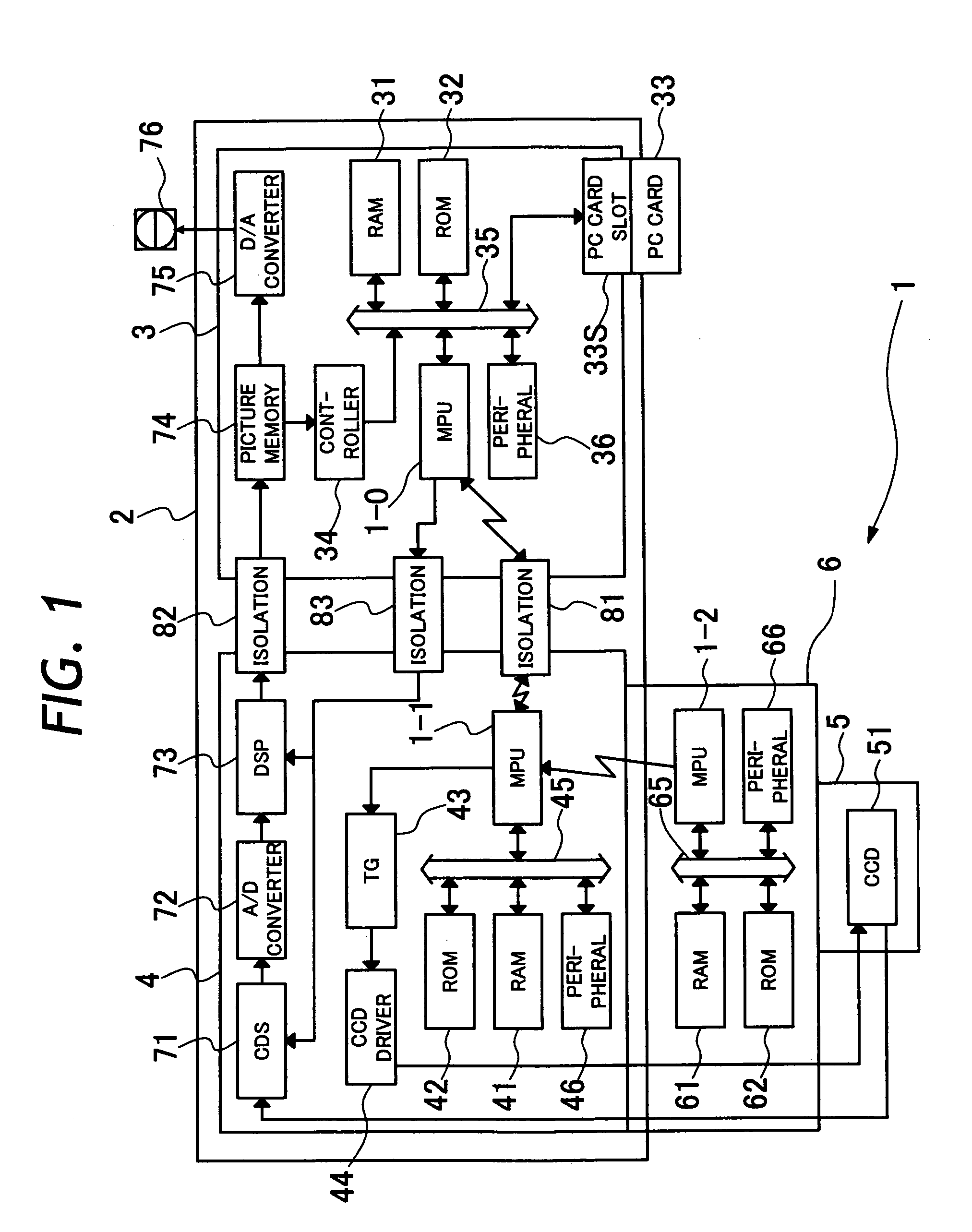
[0032]Shown diagrammatically in FIG. 1 is configuration of an electronic endoscope system 1 according to the present invention. As shown in FIG. 1, the electronic endoscope system 1 is composed of a processor 2 and a scope 5. The processor 2 is constituted by a secondary circuit 3 and a patient's circuit 4. The scope 5 is constituted by a CCD 51, and connected with the patient's circuit 4 through a scope connector 6 which is normally provided at a proximal end of a universal cable from the scope 5. According to the present invention, a PC card 33 is disconnectibly connected to a PC card slot 33S which is provided in the secondary circuit 3 of the processor 2.

[0033]The secondary circuit 3 includes MPU (Micro Processing Unit) 1-0, RAM (Random Access Memory) 31, ROM 32, PC card slot 33S, controller 34, bus 35, peripheral unit 36, picture image memory 74 and D / A converter (Digital Analog Converter) 75. On the oth...


PUM


Abstract

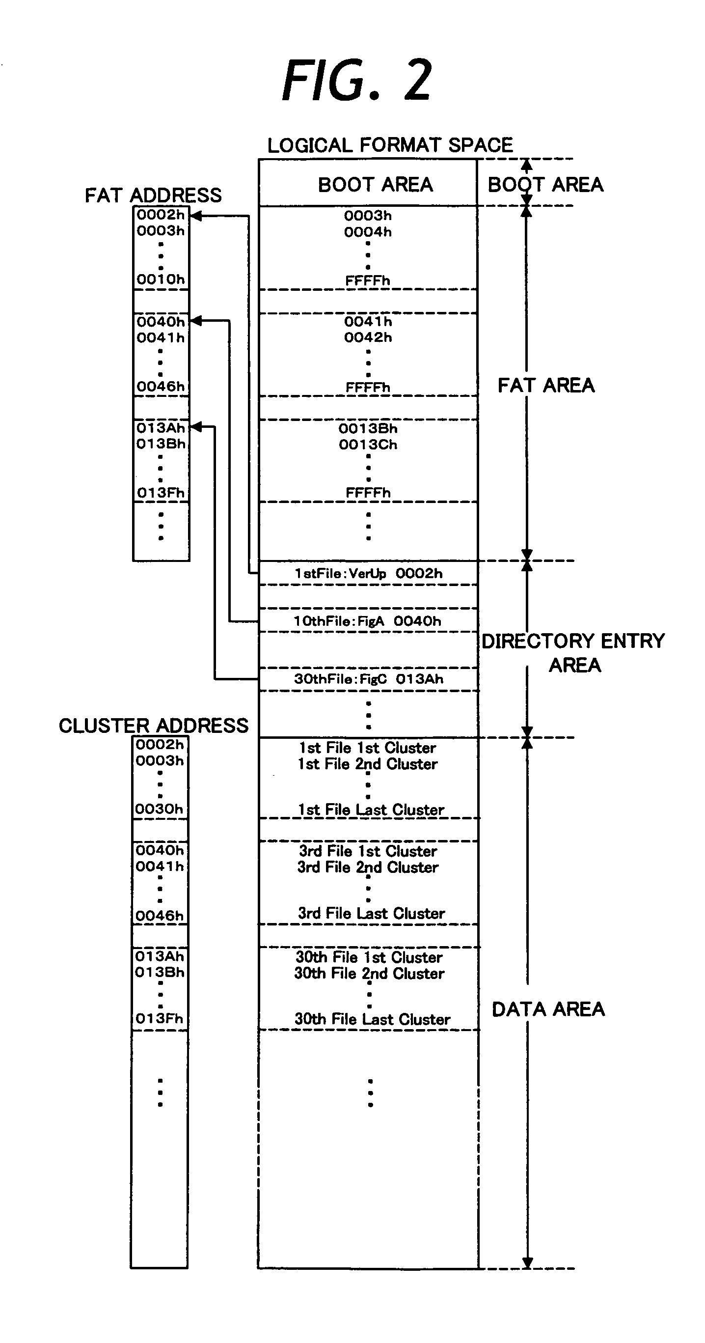
An electronic endoscope system which is largely composed of a scope and a processor. The processor includes a primary or patient's circuit and a secondary circuit which are so connected as to be able to communicate with each other for data transmission in an electrically insulated state. The secondary circuit on the side of the processor includes first MPU and first rewritable ROM which is connected with the first MPU through a first bus, a PC card slot connected to said first bus. In addition to data of picture images captured by an image sensor device mounted on a fore distal end portion of an insertion tube of a scope, a PC card stores a firmware version-up program to be executed for updating a firmware in the first ROM as soon as PC card is booted, starting from an address described in MBR of PC card. An update program of the firmware version-up program is transferred to and written into the first ROM at a high speed depending upon a clock speed of the first bus.

Description

BACKGROUND OF THE INVENTION[0001]1. Field of the Art[0002]This invention relates to an electronic endoscope system having a scope and a processor and a method for transferring programs, and more particularly to an electronic endoscope system which is operated under the control of an upgradable firmware and a method for transferring upgrading or updating programs.[0003]2. Prior Art[0004]Heretofore, electronic endoscopes have been widely in use for observation, imaging, examination or treatment of an intracavitary portion of interest by introducing an elongated narrow insertion tube into the intracavitary portion. An electronic endoscope is usually equipped with an elongated insertion tube which is generally called “scope”, and has an image sensor device, for example, like CCD (Charge Coupled Device) incorporated into a fore distal end portion of the insertion tube along with an illumination means to take picture images of an intracavitary site of interest under illuminated conditions...

Claims


Application Information

Patent Timeline
Patent Type & Authority Patents(United States)
IPC IPC(8): A61B1/00A61B1/04G02B23/24A61B1/045G06F11/00G06K17/00G06K19/00
CPCA61B1/045A61B1/042
Inventor ABE, KAZUNORI
Owner FUJI PHOTO OPTICAL CO LTD
Learn More