
Device for transmitting and/or receiving high-frequency signals in an open or closed space system

a high-frequency signal and space system technology, applied in the direction of instruments, protective material radiating elements, using reradiation, etc., can solve the problems of cracks in the material of the support structure and in the emplaced antenna element structure, and achieve the effect of compactness, resistance and inexpensiveness

Active Publication Date: 2009-09-08
EHNDRESS KHAUZER GMBKH KO KG
View PDF14 Cites 13 Cited by
  • Summary
  • Abstract
  • Description
  • Claims
  • Application Information

AI Technical Summary

Benefits of technology

[0010]An object of the invention is, therefore, to provide an inexpensive, compact and resistant device suitable for transmitting and receiving high frequency signals and distinguished by an optimized radiation characteristic.

Problems solved by technology

However, it is to be heeded that, in the manufacturing of an array antenna with curvature, no residual stresses arise, which might lead to cracks in the material of the support structure and in the emplaced antenna element structures.

Method used


Image

  • Device for transmitting and/or receiving high-frequency signals in an open or closed space system
  • Device for transmitting and/or receiving high-frequency signals in an open or closed space system
  • Device for transmitting and/or receiving high-frequency signals in an open or closed space system

Examples


Embodiment Construction

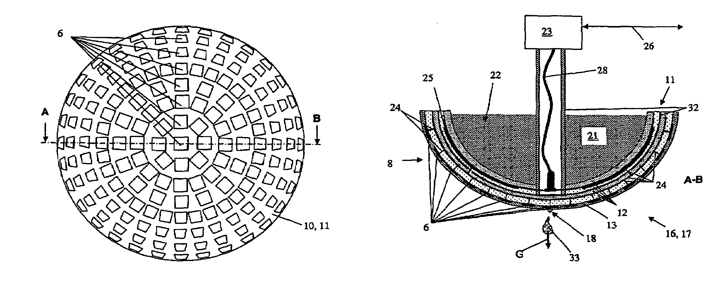
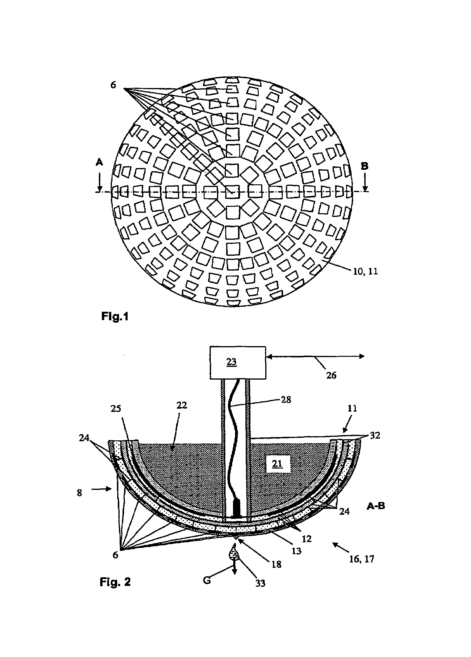
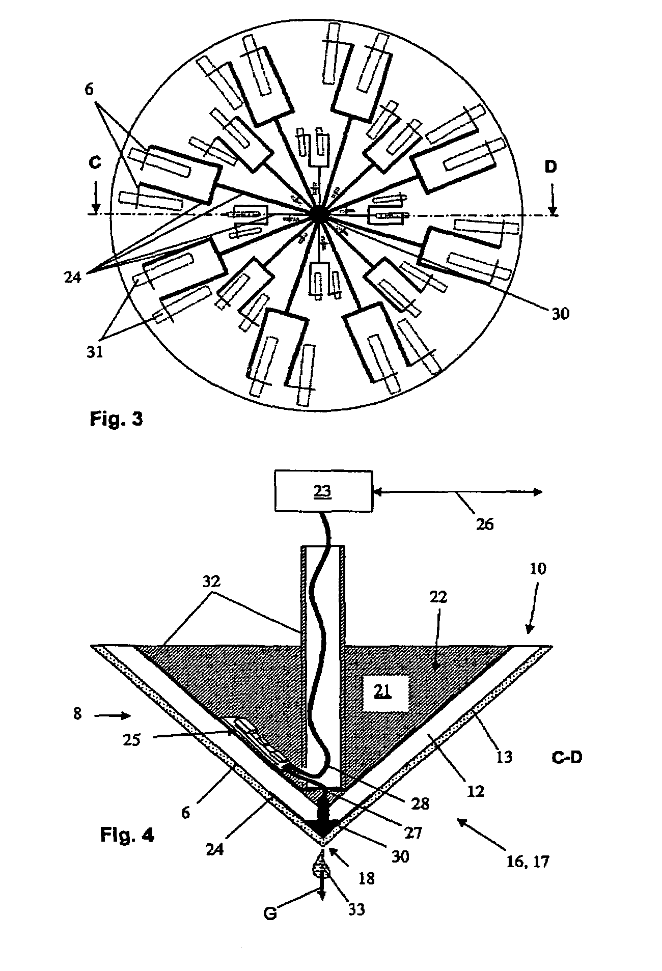
[0039]FIG. 1 shows an example of an embodiment of the array antenna 1 as a so-called patch array antenna having areal radiator elements. Antennas having a directed radiation characteristic 20, or directional effect, can be synthesized by an assembly of individual radiators, or individual antenna elements 6, to form an array or matrix. The areal radiator elements of the transmitting and receiving antenna elements 6 are arranged, for example, concentrically, or radially symmetrically. The change in the directional effect, or radiation characteristic 20, arising from the structure of the transmitting and receiving antenna elements 6 can be compensated for by the form of the array antenna 1, as shown in the sectional view of FIG. 2. The magnetic areal current densities in the coupling aperture layer 31 and antenna elements 6 is known, so that, with the help of the Green functions, the radiation characteristic of the far field of the array antenna can be ascertained. Changing the size of...


PUM


Abstract

A device for transmitting and / or receiving high-frequency signals in an open or closed, spatial system, wherein the device is embodied as an array antenna, which transmits and receives high-frequency signals with a specified form of wavefront. The array antenna comprises a support structure with transmitting and / or receiving antenna elements. The support structure comprises a dielectric material, wherein a transmitting / receiving unit is provided, at least one feeding network is provided for transferring the high-frequency signals between the transmitting / receiving unit and the transmitting and / or receiving, antenna elements, and wherein a control / evaluation unit is provided. The device provides an inexpensive, compact and resistant device for transmitting and receiving high-frequency signals, which is distinguished by an optimized radiation characteristic.

Description

TECHICAL FIELD[0001]The present invention relates to a device for transmitting and / or receiving high-frequency signals in an open or closed, spatial system, wherein the device is embodied as an array antenna, which transmits and receives the high-frequency signals with a specified, or predetermined, form of wavefront, wherein the array-type antenna is embodied as a support structure with transmitting and / or receiving antenna elements, wherein the support structure is made of a dielectric material, wherein a transmitting / receiving unit is provided, wherein at least one feeding network is provided for transferring high-frequency signals between the transmitting / receiving unit and the transmitting and / or receiving antenna elements, and wherein a control / evaluation unit is provided.BACKGROUND DISCUSSION[0002]One of many measuring methods for ascertaining fill level in a container is the travel-time measuring method. In the travel-time measuring method, for example, microwaves, or radar ...

Claims


Application Information

Patent Timeline
Patent Type & Authority Patents(United States)
IPC IPC(8): G01R29/10
CPCH01Q1/40H01Q1/225G01F23/284
Inventor MULLER, ROLAND
Owner EHNDRESS KHAUZER GMBKH KO KG
Learn More