Eyepiece for head mounted display system and method of fabrication

Active Publication Date: 2009-09-08
BAE SYST INFORMATION & ELECTRONICS SYST INTERGRATION INC
View PDF24 Cites 23 Cited by
  • Summary
  • Abstract
  • Description
  • Claims
  • Application Information

AI Technical Summary

Benefits of technology

[0011]In a preferred embodiment, the diffractive optical element is formed on the first surface located as far away from the user's eye as possible. This configuration minimi

Problems solved by technology

The head-mounted displays, however, pose two challenges that have made simple eyepieces unsuitable.
The first challenge is the need for a large field of view and long eye relief, i.e., distance between the eye and the first optical element.
These two opposing requirements place a geometric limitation on the eyepiece design.
It is well known in the art that it is not possible to provide color aberration correction with only one powered refractive lens material.
This adds significant co

Method used


Image

  • Eyepiece for head mounted display system and method of fabrication
  • Eyepiece for head mounted display system and method of fabrication
  • Eyepiece for head mounted display system and method of fabrication

Examples


second embodiment

[0065]FIG. 5 shows an eyepiece 100-2 that has been constructed according to the principles of the present invention.

[0066]This second embodiment eyepiece 100-2 can also be made monolithic. It preferably incorporates an aspheric and a diffractive optical element (DOE) surface that together can yield excellent eyepiece performance over a large field of view and relatively long eye relief distance. This element needs only two powered surfaces, as opposed to the three of the prior art, and achieves full color correction via the DOE surface. The reflective surface simply provides mechanical folding and is not optically significant otherwise, in a current preferred embodiment. The element does not require any optical anti-reflection coatings, though they may be added to improve stray light rejection. If the element is made of a plastic material, it can be readily manufactured either directly by diamond turning or by a mold process wherein a metal mold master is diamond turned.

[0067]In mor...

third embodiment

[0079]FIG. 8 shows an eyepiece 100-3 that has been constructed according to the principles of the present invention.

[0080]This third embodiment provides full color correction and simultaneous imaging of two separate focal planes by means of a single, monolithic element.

[0081]In more detail, light 114 originates either at surface 110, which is the location of the flat panel display source surface 112, or light 714 at surface 710.

[0082]In one example, surface 710 represents the light output from the phosphor output of an image intensifier tube. Specifically, surface 710 shows the typical 40 mm radius of curvature over the 18 mm format diameter of an intensifier tube output.

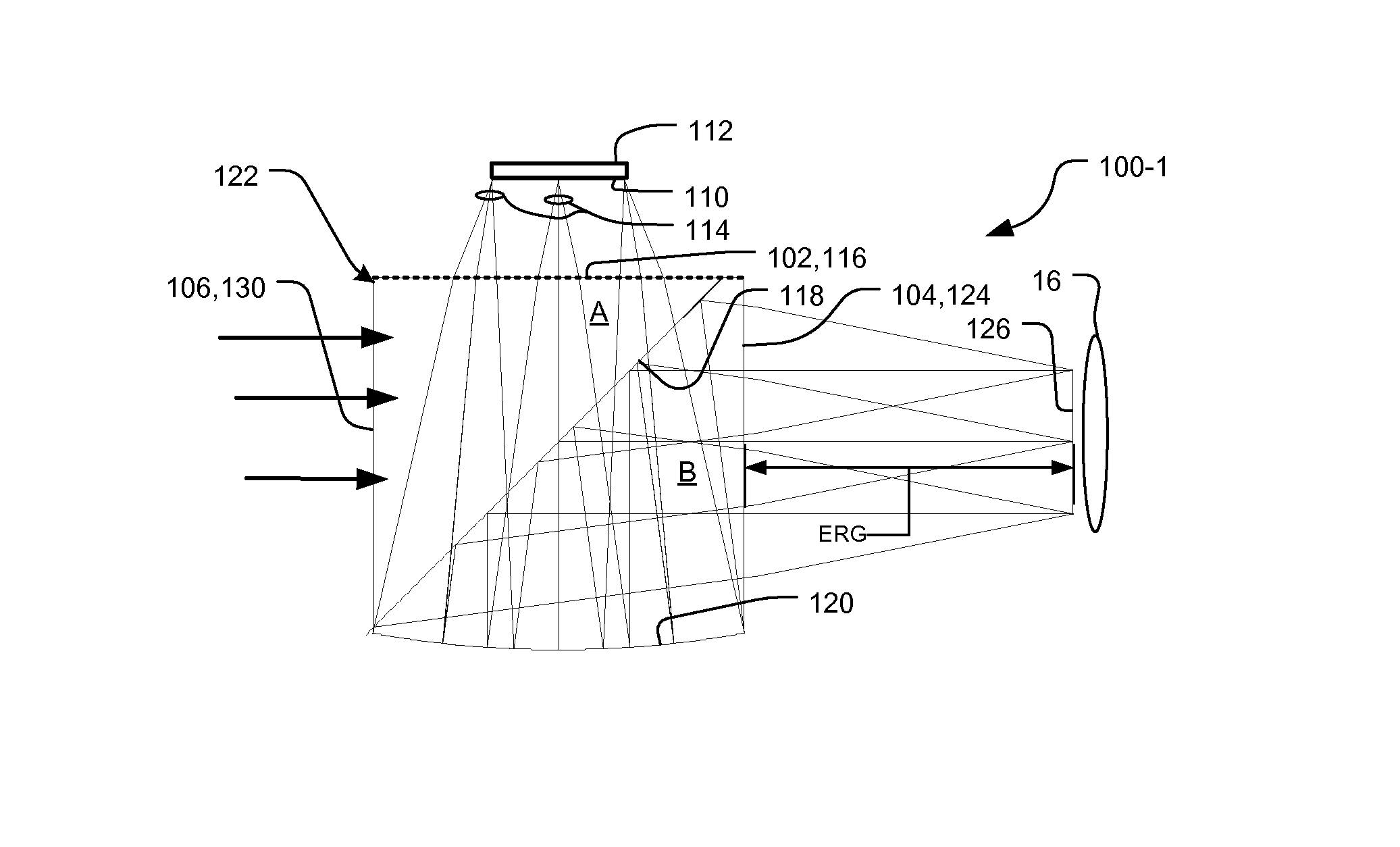
[0083]Light then passes into the monolithic element body 122 through either the upper asphere / diffractive surface 116 functioning as the display entrance port 102 or straight-through asphere / diffractive surface 716 functioning as environment entrance port 106. Both surfaces are fabricated onto a solid, optically tra...

first embodiment

[0095]In step 1112, the inverses of one or more diffractive surfaces, for example surface 116 of the first embodiment, are formed in the mold according to a first fabrication option. Presently, this might be accomplished with diamond turning or other microfabrication techniques such as lithography with or without chemical or ion etching.

[0096]In step 1114, the mold is filled with the plastic or other material for the body 122 in a compression or injection molding process, for example.

[0097]In step 1116, the body 122 is ejected after sufficient material solidification.

[0098]In step 1118, if a second fabrication option is pursued as an alternative to the first option, the diffractive optical element, such as element 116 in the first embodiment, is added to the body. In one example, an embossing process is used, in which the diffractive element 116 is impressed into the body by local deformation (e.g., heated stamping UV curing to facilitate deformation) or in a thin layer of material ...


PUM


Abstract

A monolithic optical element for an eyepiece in a head mounted display system has a body, in which a first surface of the body receives light from a display device, the light passes through a second surface of the body to an eye of a user, and a reflective folding surface is located optically between the first surface and the second surface. The reflective folding surface folds an optical path between the first surface and the second surface. Finally, a diffractive optical element is provided on at least one of the first surface or the second surface. The use of the diffractive optical surface enables the eyepiece element to be constructed of a single optical substrate material, yet function over a broad color spectrum with superior resolution and minimal distortion over a large field of view.

Description

RELATED APPLICATIONS[0001]This application claims the benefit under 35 USC 119(e) of U.S. Provisional Application Nos. 60 / 745,352, filed on Apr. 21, 2006, 60 / 745,260, filed on Apr. 20, 2006 and 60 / 744,839, filed on Apr. 14, 2006, all three of which are incorporated herein by reference in their entirety.BACKGROUND OF THE INVENTION[0002]There are a variety of applications for head-mounted display systems. These systems typically include image displays such as micro-flat-panel display devices based on organic light emitting diode (OLED) technology or active-matrix liquid crystal display (AMLCD) technology, for example. The systems also include eyepieces that couple the light from the display devices and possibly light from the environment to the users' eyes.[0003]The head-mounted display systems are applied to the military, in field operations and simulations, medical procedures, and industrial maintenance operations. There are now also opportunities to use head-mounted displays for ga...

Claims


Application Information

Patent Timeline
IPC IPC(8): G02B25/00G02B27/10
CPCG02B5/1814G02B17/086G02B27/42G02B27/4211G02B27/0172G02B2027/0116
Inventor HALL, JOHN M.
Owner BAE SYST INFORMATION & ELECTRONICS SYST INTERGRATION INC
Why Eureka
Try Eureka