Interconnection inverter device

a technology of inverter and inverter, which is applied in the direction of electric variable regulation, process and machine control, instruments, etc., can solve the problems of shock, difficulty in adopting home electric appliances, etc., and achieve the effect of safe stopping the devi

Inactive Publication Date: 2009-09-08
MITSUBISHI ELECTRIC CORP
View PDF22 Cites 15 Cited by
  • Summary
  • Abstract
  • Description
  • Claims
  • Application Information

AI Technical Summary

Benefits of technology

[0013]The interconnection inverter device according to the present invention includes a pair of capacitors connected in series between a pair of direct-current buses each connecting the direct-current power supply and the inverter, and controls opening or closing of the opening / closing unit inserted to either one of the positive-electrode-side bus and the negative-electrode-side bus based on the monitor voltages obtained by monitoring terminal voltages of the pair of capacitors. Therefore, even if a short-circuit fault occurs in a capacitor, it is possible to prevent a situation, which may arise, where a high voltage is applied to a normal capacitor, and to safely stop the device.

Problems solved by technology

However, the electrolytic capacitor with such a high-breakdown voltage is not common in terms of its cost and configuration, and it is, therefore, difficult to be adopted into home electric appliances.
The condition is such that he / she may get a shock upon operation of a detection function for preventing the device from being destroyed caused by overvoltage or overcurrent occurring inside the interconnection inverter device, because the device is in the stopped state in which the charge in an output capacitor connected to a final stage of the device is not being discharged.

Method used


Image

  • Interconnection inverter device
  • Interconnection inverter device
  • Interconnection inverter device

Examples


first embodiment

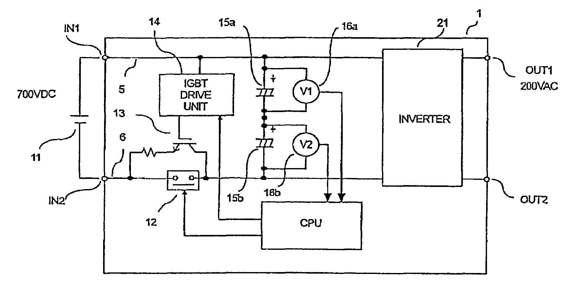
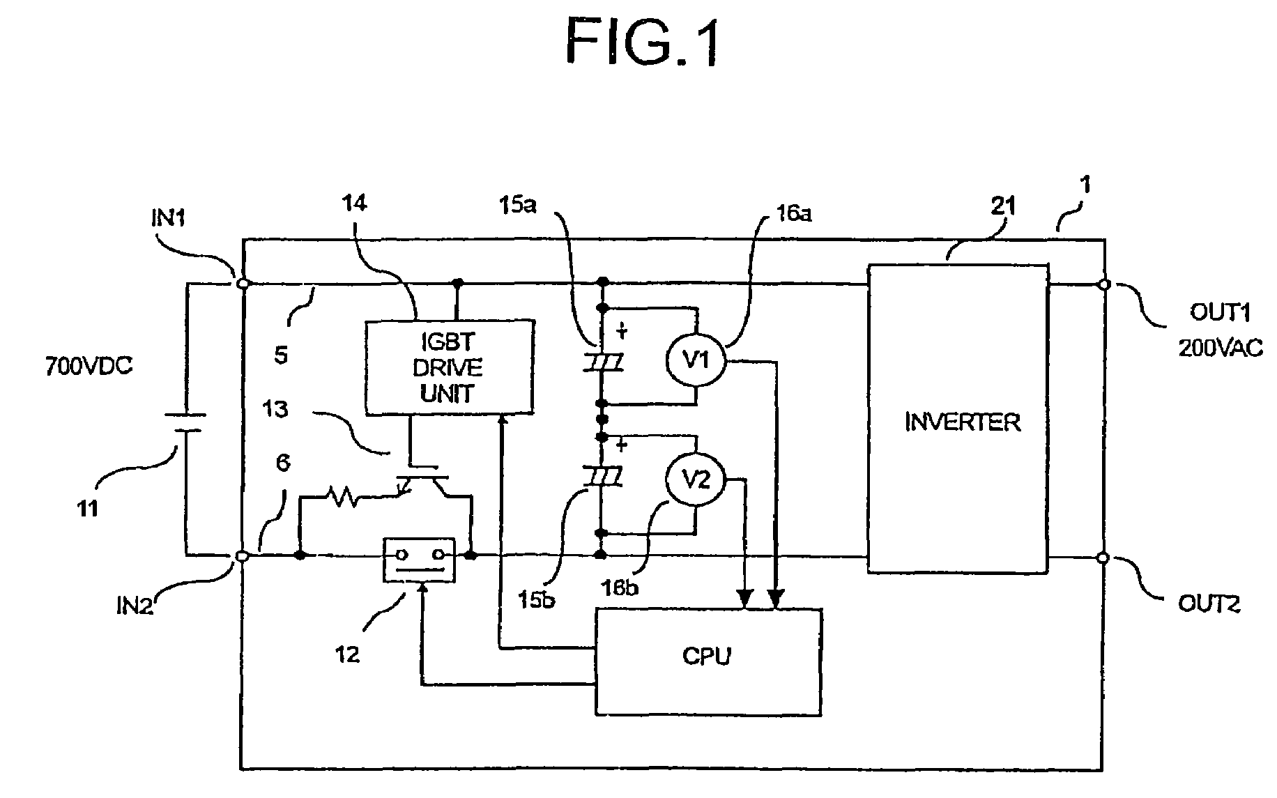
[0032]FIG. 1 is a circuit diagram of an interconnection inverter device 1 according to a first embodiment of the present invention. The interconnection inverter device 1 is configured as a power system in such a manner that its input terminals IN1 and IN2 are connected to a solar cell 11 which is a direct-current power supply and power is interconnected to an alternating-current power system (not shown) through its output terminals OUT1 and OUT2 which are alternating current output terminals. In the solar cell 11 as the direct-current power supply, serial and parallel combinations of cells can arbitrarily be configured. Therefore, an output voltage can be set in a wide range from tens of VDC to hundreds of VDC.

[0033]The circuit configuration of the interconnection inverter device 1 according to the first embodiment shown in FIG. 1 is explained below. The interconnection inverter device 1 includes component units such as an inverter 21, a switching element 13 such as IGBT (Insulated ...

second embodiment

[0045]FIG. 3 is a circuit diagram of an interconnection inverter device 30 according to a second embodiment of the present invention. The interconnection inverter device 30 is configured, based on the configuration according to the first embodiment of FIG. 1, to include a converter 25, which changes (to boost voltage and / or to step down voltage) an input voltage supplied from the solar cell 11, provided in the input stage of the inverter 21. The rest parts of the configuration are the same as or equivalent to these of the configuration according to the first embodiment shown in FIG. 1, and therefore, the same reference numerals are assigned to those component units, and explanation thereof is omitted.

[0046]In FIG. 3, the converter 25 includes coils 17a and 17b, switching elements 18a and 18b such as IGBT, diodes 19a and 19b, and capacitors 20a and 20b. In the converter 25, the switching element 18a and the switching element 18b are connected in series to be inserted between the bus ...

third embodiment

[0051]FIG. 4 is a circuit diagram of an interconnection inverter device 40 according to a third embodiment of the present invention. The interconnection inverter device 40 is configured, based on the configuration according to the first embodiment of FIG. 1, so that three or more capacitors (three in the example of FIG. 4) are inserted between the bus 5 and the bus 6. The rest parts of the configuration are the same as or equivalent to these of the configuration according to the first embodiment shown in FIG. 1, and therefore, the configuration except the main component units is omitted from FIG. 4, and explanation thereof is omitted.

[0052]In FIG. 3, the capacitors 15a, 15b, and a capacitor 15c (C1, C2, C3) are connected in series to be inserted between the bus 5 and the bus 6. Based on this configuration, even if a short-circuit fault occurs in any one of the capacitors, the breakdown voltage can be ensured by the remaining two capacitors. If three or more capacitors are connected,...


PUM


Abstract

An interconnection inverter device includes a pair of capacitors connected in series to a pair of direct-current buses each connecting a direct-current power supply and the inverter; an opening / closing unit connected to either one of the pair of direct-current buses; voltage monitor units that monitor terminal voltages of the pair of capacitors respectively; and a controller that controls opening or closing of the opening / closing unit based on monitor voltages detected by the voltage monitor units.

Description

TECHNICAL FIELD[0001]The present invention generally relates to an inverter device. The present invention specifically relates to an interconnection inverter device for interconnecting direct-current power from a solar cell, a fuel cell, or the like, to an alternating-current power system.BACKGROUND ART[0002]Interconnection inverter devices for interconnecting with an alternating-current power system include a smoothing unit for stabilizing a voltage of input direct-current power. The smoothing unit has conventionally been configured by using an electrolytic capacitor for high power.[0003]On the one hand, among interconnection inverter devices in which the direct-current power is an output of a solar cell, an interconnection inverter device with a high-voltage specification, such that an input voltage reaches even 700 VDC, requires a product with a high-breakdown voltage of about 850 WV (working voltage) allowing for derating as a breakdown voltage of an electrolytic capacitor for s...

Claims


Application Information

Patent Timeline
Patent Type & Authority Patents(United States)
IPC IPC(8): H02M7/53862H02H7/122
CPCH02H7/1225H02M7/487Y02E10/56H02H7/16
Inventor TOBA, MASAHIROMATSUBARA, NORIYUKIKAGEYAMA, MASANORINISHIO, NAOKI
Owner MITSUBISHI ELECTRIC CORP
Why Eureka
Try Eureka