Polyethylene compositions and pipe made from same

a technology of polyethylene compositions and pipes, applied in the field of polyethylene compositions, can solve problems such as expensive repair of cracks or breaks, and achieve the effect of high load melt index

Active Publication Date: 2009-09-15
CHEVRON PHILLIPS CHEMICAL CO LP
View PDF31 Cites 32 Cited by
  • Summary
  • Abstract
  • Description
  • Claims
  • Application Information

AI Technical Summary

Benefits of technology

[0067]The invention having been generally described, the following examples are given as particular embodiments of the invention and to demonstrate the practice and advantages thereof. It is understood that the examples are given by way of illustration and are not intended to limit the specification of the claims in any manner.

Problems solved by technology

Such pipes are exposed to numerous stresses during their lifetime that may result in cracks or breaks that are expensive to repair, especially in situations where the pipe is buried in a structure or underground.
However, pipes for high-pressure gas transport applications must also have adequate resistance to slow crack growth (SCG) as this is the most common mode of failure for pipes in service.

Method used


Image

  • Polyethylene compositions and pipe made from same
  • Polyethylene compositions and pipe made from same
  • Polyethylene compositions and pipe made from same

Examples


example 1

[0068]Alumina A, from W.R. Grace Company, was impregnated to incipient wetness with an aqueous solution of ammonium sulfate. Typically, the alumina had a surface area of about 330 m2 / gram and a pore volume of about 1.3 cc / gram. The amount of ammonium sulfate used was equal to 20% of the starting alumina. The volume of water used to dissolve the ammonium sulfate was calculated from the total pore volume of the starting sample (i.e. 2.6 mLs of water for each gram of alumina to be treated). Thus, a solution of about 0.08 grams of ammonium sulfate per mL of water was employed. The resulting wet sand was dried in a vacuum oven overnight at 120° C., and then screened through a 35-mesh screen. Finally, the material was activated in a fluidizing stream of dry air at 550° C. for 3 hours, in the case of bench scale samples, or 6 hours, for the larger pilot plant samples. The samples were then stored under nitrogen.

[0069]The PE compositions of Table 1 of this disclosure were produced in a 27.3...

example 2

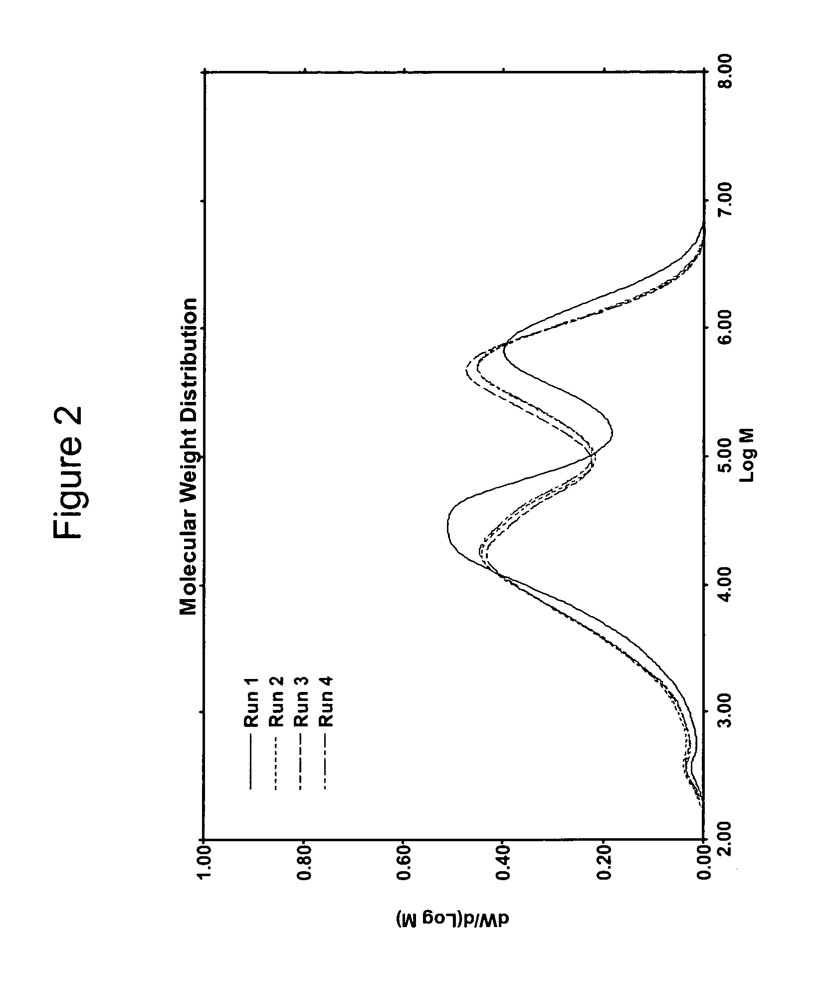
[0075]The differential weight fraction MWD was determined for the PE compositions prepared under conditions specified in Table 1 are shown in FIG. 2 respectively. The figures show the resulting PE compositions to have two peaks corresponding to a bimodal PE composition.

example 3

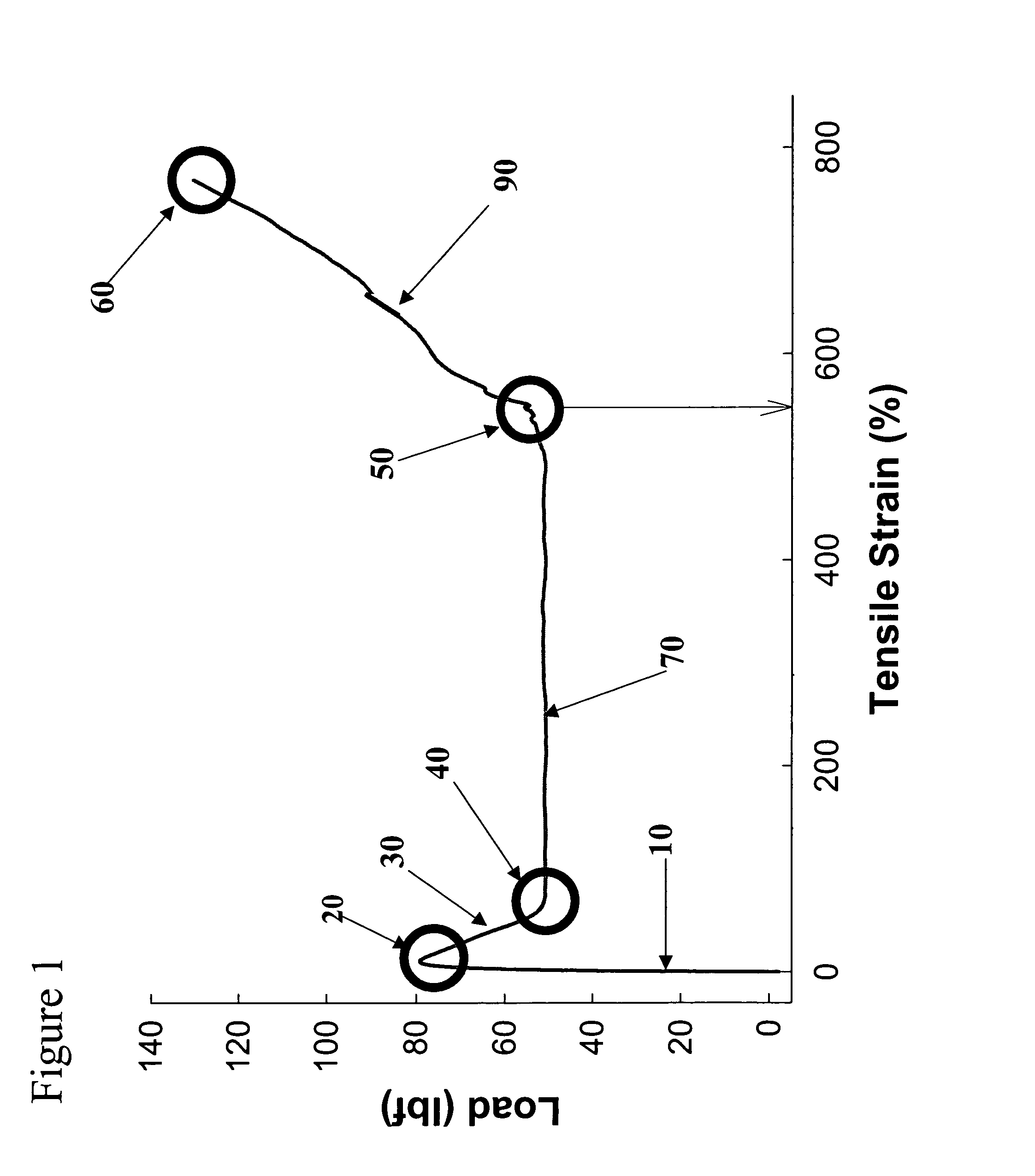
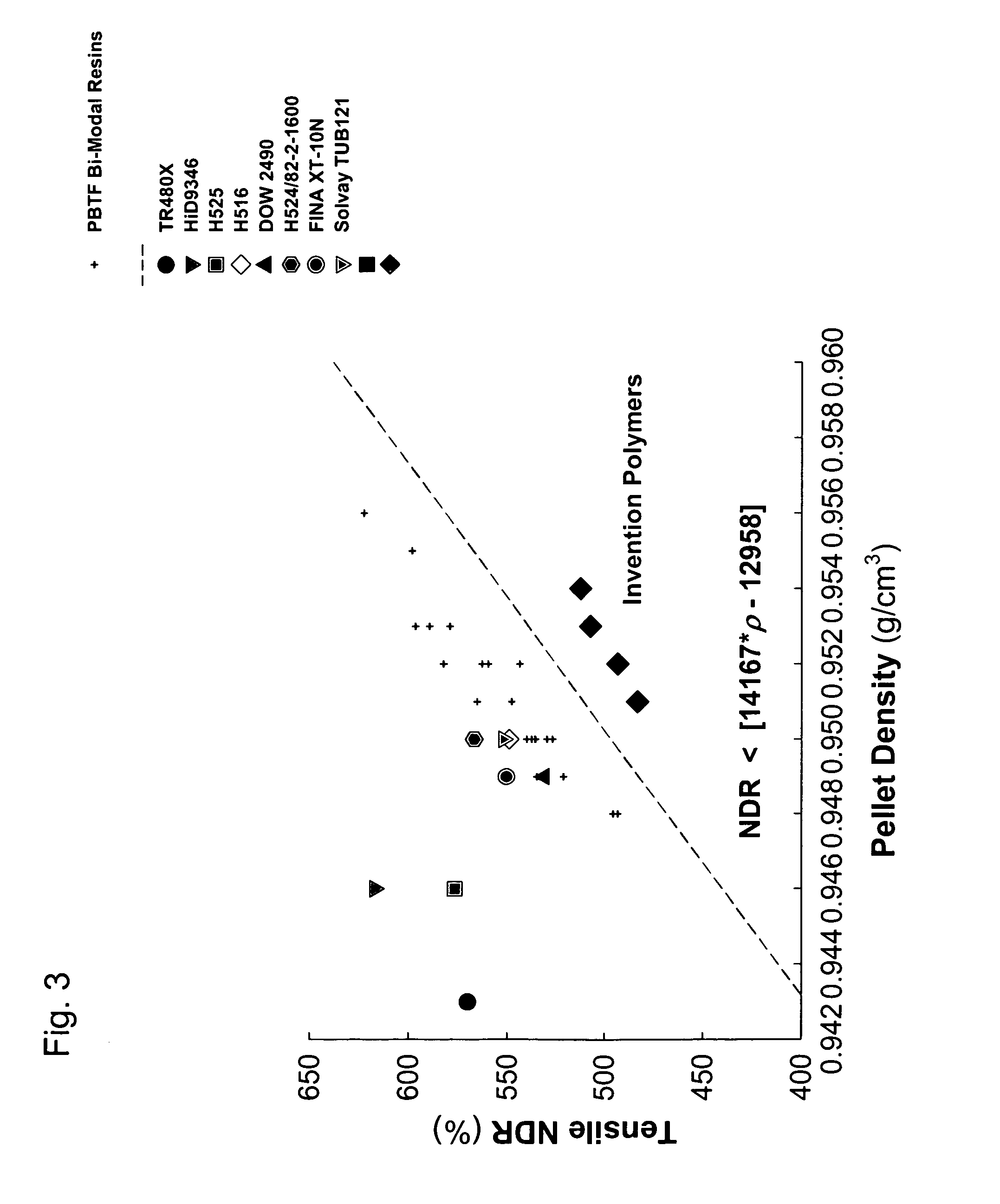
[0076]Select mechanical properties of the PE compositions of this disclosure (Table 1) along with a few commercially available pressure pipe-grade HDPE resins are listed in Table 2. The tensile NDR of the PE compositions of this disclosure were determined as a function of their density, yield stress and HLMI. In all cases tensile tests of the PE compositions (compression molded by slow cooling from the molten state) were performed using die-cut ASTM Type IV specimens using an Instron tensile tester. Tests at room temperature were performed in accordance with ASTM D 638-00 using a crosshead speed of 51 mm / min.

[0077]

TABLE 2CharpyTensileTensileTensileImpactHigh-YieldBreakNDREnergyStressDensityStressStress(Percent@ 23° C.CharpyPENTPENTResin ID(g / cc)(MPa)(MPa)Strain)(J)Tdb (° C.)(h)(h)TR480X0.94322.931.0569.9HiD93460.94623.731.8617.10.34−20~1000~450H5160.95025.540.0549.11.90−35~3000~500DOW24900.94925.837.1531.01.70−35~5000~2200Inventive0.95427.032.3512.41.28−35>7000>7000Run 1Inventive0.9...


PUM

PropertyMeasurementUnit
densityaaaaaaaaaa
load melt indexaaaaaaaaaa
failure timeaaaaaaaaaa

Abstract

A polymer composition comprising a density equal to or greater than about 0.947 g / cc, a high load melt index from about 1 g / 10 min to about 30 g / 10 min, and a tensile natural draw ratio less than about 14167 ρ-12958, where ρ is the density (g / cc) of the composition. A polymer composition comprising a tensile natural draw ratio less than about 14167ρ-12958, where ρ is the density (g / cc) of the composition and wherein less than about 1 weight percent of the composition comprises non-polymeric additives.

Description

CROSS-REFERENCE TO RELATED APPLICATIONS[0001]The subject matter of the present application is related to U.S. patent application Ser. No. 11 / 264,900 filed on Nov. 2, 2005, now U.S. Patent Application Publication No. US 2007-0043182 A1, and entitled “Multimodal Polyethylene Compositions and Pipe Made From Same,” and Ser. No. 11 / 359,972 filed on Feb. 22, 2006, now U.S. Patent Application Publication No. US 2007-0197374 A1, and entitled “Dual Metallocene Catalysts for Polymerization of Bimodal Polymers,” each of which is hereby incorporated herein by reference in its entirety for all purposes.FIELD OF THE INVENTION[0002]The present disclosure relates to polymer compositions and pipe made from same, more specifically to polyethylene compositions for the manufacture of high-pressure rated pipe.BACKGROUND OF THE INVENTION[0003]Polymeric pipes have replaced metal pipes in many applications such as for high-pressure fluid and natural gas transportation. Polymeric pipes have several advantag...

Claims


Application Information

Patent Timeline
Patent Type & Authority Patents(United States)
IPC IPC(8): C08F10/02C08F210/16C08L23/06F16L9/12
CPCC08F210/16C08L23/06C08L101/00F16L9/127Y10T428/13Y10T428/1386C08L2666/06C08F210/14C08F2500/04C08L23/0815C08F10/02
Inventor KRISHNASWAMY, RAJENDRA K.YANG, QINGROHLFING, DAVID C.MCDANIEL, MAX P.JAYARATNE, KUMUDINI C.FRENCH, JIM E.
Owner CHEVRON PHILLIPS CHEMICAL CO LP
Why Eureka
Try Eureka