
Nanotip electrode electroluminescence device with contoured phosphor layer

a phosphor layer and electroluminescence technology, applied in the direction of electrode system manufacturing, electric discharge tube/lamp manufacturing, discharge tube luminescnet screens, etc., can solve the problems of bulk silicon being considered highly inefficient light emitters, poor light generation efficiency, and conventionally unsuitable for optoelectronic applications. , to achieve the effect of increasing the surrounding electric field and enhancing the surface charge density

Inactive Publication Date: 2009-09-15
SHARP KK
View PDF7 Cites 7 Cited by
  • Summary
  • Abstract
  • Description
  • Claims
  • Application Information

AI Technical Summary

Benefits of technology

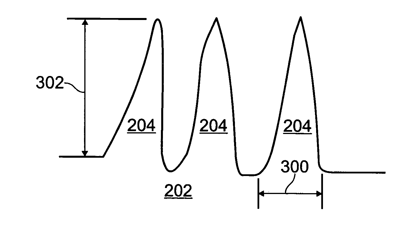
[0012]Described herein is an application of a nanostructured nanorod material bottom electrode for an EL device. Although ITO has long been used as an electrode for these devices, it has typically been planar in character. It is well known that the surface charge density is enhanced at sharp geometries in conductors, increasing the surrounding electric field. It has recently been shown that sharp geometry nanostructural materials such as nanotubes and nanowires are efficient field emitters.
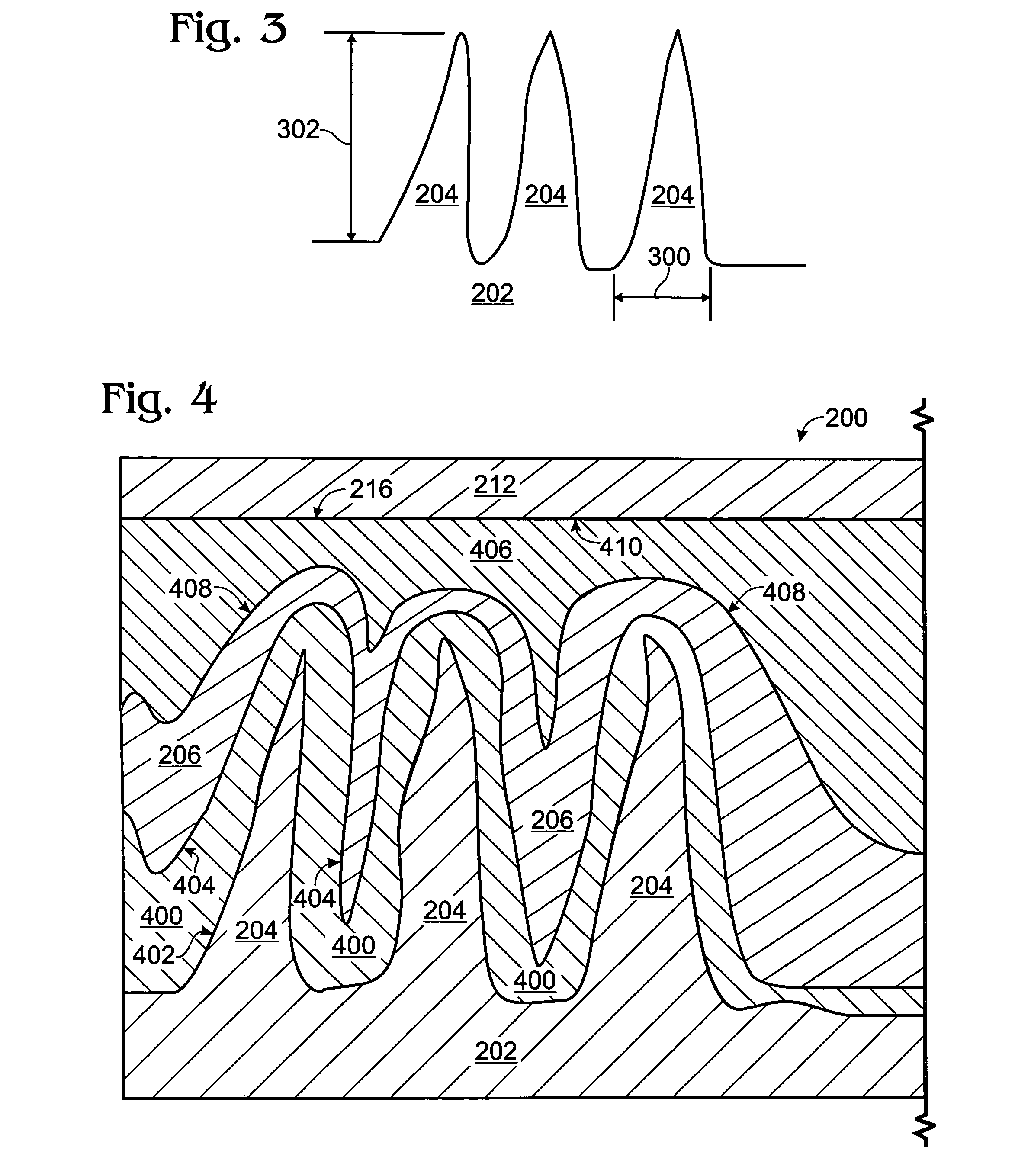
[0013]The nanostructured ITO electrode is covered with nanorods. These are rod-shaped, sharp-tipped nanostructures that serve to enhance the field emission of electrons into the phosphor layer of these devices. This electrode permits a reduction in the operating voltage and in the luminescence threshold of these EL devices. Further, the phosphor material overlying the electrode is contoured to approximately match the shape of the nanorods.

Problems solved by technology

For silicon devices, the light generation efficiency is known to be poor and the photon energy is predominantly around 2 eV.
However, these devices are fabricated on materials that are typically not compatible with silicon, for example type III-V materials such as InGaN, AlGaAs, GaAsP, GaN, and GaP.
Silicon has conventionally been considered unsuitable for optoelectronic applications, due to the indirect nature of its energy band gap.
Bulk silicon is indeed a highly inefficient light emitter.
However, the high surface area inherent to a nanostructures creates problems in conformally covering the nanotip surfaces.
This conformality problem, in turns, can result in the formation of gaps and air pockets between the nanotip electrode and the overlying phosphor layer.

Method used


Image

  • Nanotip electrode electroluminescence device with contoured phosphor layer
  • Nanotip electrode electroluminescence device with contoured phosphor layer
  • Nanotip electrode electroluminescence device with contoured phosphor layer

Examples


Embodiment Construction

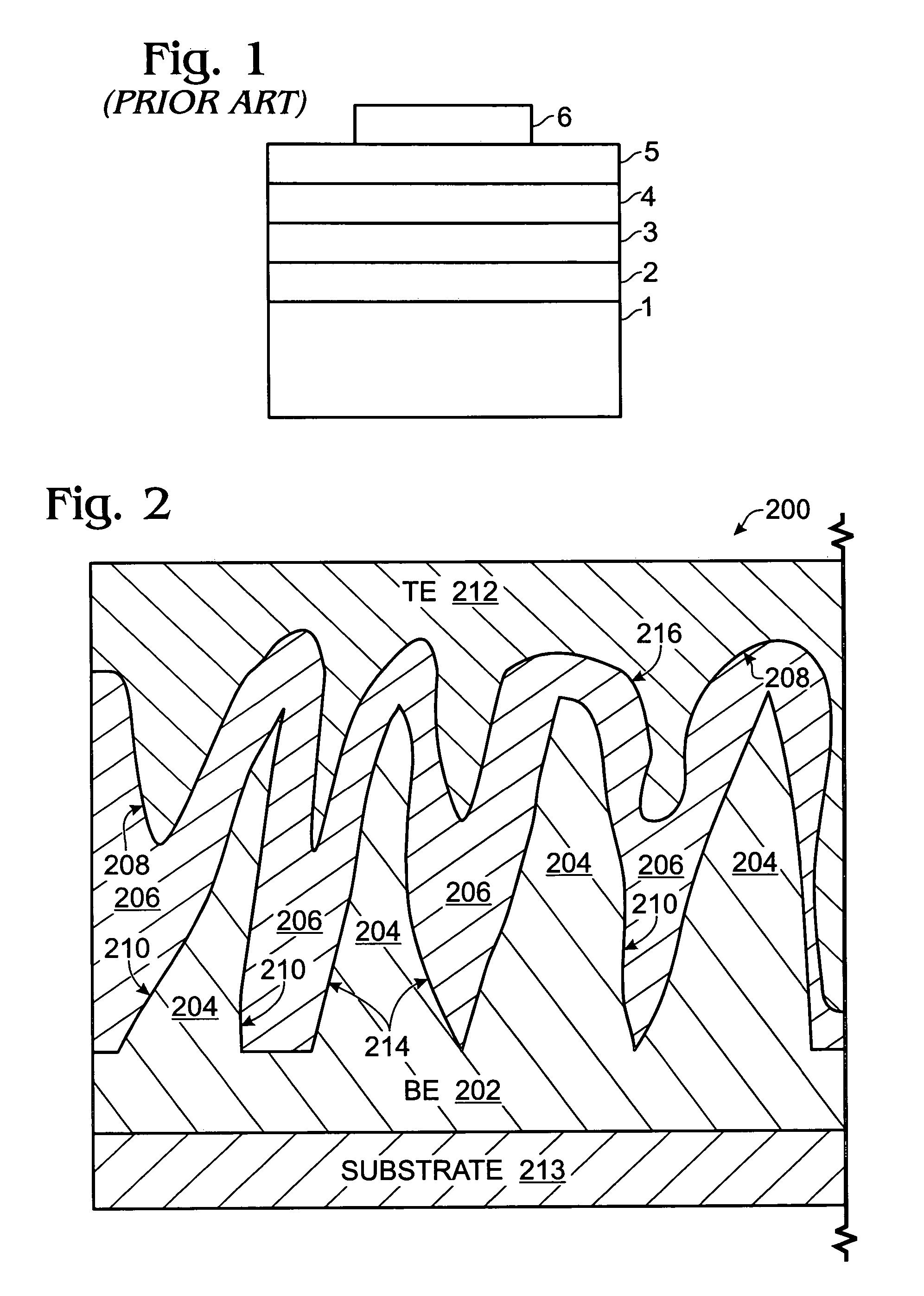
[0025]FIG. 2 is a partial cross-sectional, detailed view of an electroluminescence (EL) device with a nanotip-contoured phosphor layer. The EL device 200 comprises a bottom electrode (BE) 202 with nanotips 204. A phosphor layer 206 overlies the bottom electrode 202, having an irregularly-shaped top surface 208 and an irregularly-shaped bottom surfaces 210. A top electrode 212 overlies the phosphor layer 206.

[0026]A substrate 213 underlies the bottom electrode 202, made from a material such as silicon, silicon oxide, silicon nitride, glass, quartz, or plastic. In one aspect, the substrate 213, bottom electrode 202, and nanotips 204 are a transparent material, while the top electrode is a non-transparent material. In another aspect, the top electrode 212 is transparent, while the bottom electrode 202 and substrate 213 are non-transparent. In yet another aspect, the substrate 213, bottom electrode 202, and top electrode 212 are all transparent.

[0027]As used herein, the word “nanotip” i...


PUM


Abstract

A device and a fabrication method are provided for an EL device with a nanotip-contoured phosphor layer. The method comprises: forming a bottom electrode with nanotips; forming a phosphor layer overlying the bottom electrode, having irregularly-shaped top and bottom surfaces; and, forming a top electrode overlying the phosphor layer. The bottom electrode top surface has a nanotip contour, and the phosphor layer irregularly-shaped top and bottom surfaces have contours approximately matching the bottom electrode top surface nanotip contour. In one aspect, a contoured bottom dielectric is interposed between the bottom electrode and the phosphor layer, having top and bottoms surfaces with contours approximately matching the nanotip contour. Likewise, a top dielectric may be interposed between the top electrode and the phosphor layer, having a bottom surface with a contour approximately matching the contour of phosphor layer top surface.

Description

BACKGROUND OF THE INVENTION[0001]1. Field of the Invention[0002]This invention generally relates to integrated circuit (IC) fabrication and, more particularly, to an electroluminescence (EL) device made using a nanotip electrode, with a nanotip-contoured phosphor layer.[0003]2. Description of the Related Art[0004]The generation of light from semiconductor devices is possible, regardless of whether the semiconductor material forms a direct or indirect bandgap. High field reverse biased p-n junctions create large hot carrier populations that recombine with the release of photons. For silicon devices, the light generation efficiency is known to be poor and the photon energy is predominantly around 2 eV. The conversion of electrical energy to optical photonic energy is called electroluminescence (EL). Efficient EL devices have been made that can operate with small electrical signals, at room temperature. However, these devices are fabricated on materials that are typically not compatibl...

Claims


Application Information

Patent Timeline
Patent Type & Authority Patents(United States)
IPC IPC(8): H05B33/26
CPCB82Y20/00C09K11/54H05B33/14H05B33/10C09K11/642H01L33/18
Inventor CONLEY, JR., JOHN F.EVANS, DAVID R.GAO, WEIONO, YOSHI
Owner SHARP KK
Learn More