Device for and method of estimating motion in video encoder

a motion estimator and video technology, applied in signal generators with optical-mechanical scanning, color televisions with bandwidth reduction, etc., can solve the problems of high computing intensity of algorithms, prohibitive computation costs for software implementations, and limited search ranges, so as to reduce the amount of calculation required, the operating time of the motion estimator and its power consumption

Inactive Publication Date: 2009-09-15
SAMSUNG ELECTRONICS CO LTD
View PDF1 Cites 61 Cited by
  • Summary
  • Abstract
  • Description
  • Claims
  • Application Information

AI Technical Summary

Benefits of technology

[0017]The present invention provides a motion estimator of a video encoder and a motion estimation method, which is capable of reducing the operating time of the motion estimator and its power consumption by varying a search region for a partial search of medium and lower steps in an MRMCS algorithm and by thereby, substantially, reducing the amount of calculation required for a motion estimation.

Problems solved by technology

A full search block matching algorithm (FSBMA) as a basic method is optimum from an aspect of performance, but this algorithm is highly computing intensive and requires the use of special-purpose architectures to obtain real-time performance.
On the other hand, the search range must be limited for practical purpose due to high complexity involved in the computation of motion estimation.
This computation cost is prohibitive for software implementations.
Such a motion estimation method may repair the damaged data to increase the resolution of video blocks and overall video encoding speed as compared with the fixed step size, however, the motion estimation for all macroblocks requires the performance of much calculation, which also causes a prolonged operating time of a motion estimator and much power consumption.

Method used


Image

  • Device for and method of estimating motion in video encoder
  • Device for and method of estimating motion in video encoder
  • Device for and method of estimating motion in video encoder

Examples


Embodiment Construction

[0034]Hereinafter, preferred embodiments of the present invention will be described in detail with reference to FIGS. 2 through 10. For purposes of clarity, a detailed description of functions and systems known to persons skilled in the art have been omitted.

[0035]With reference to FIGS. 2 through 10, the operation of exemplary embodiments of the present invention will be described in detail, as follows.

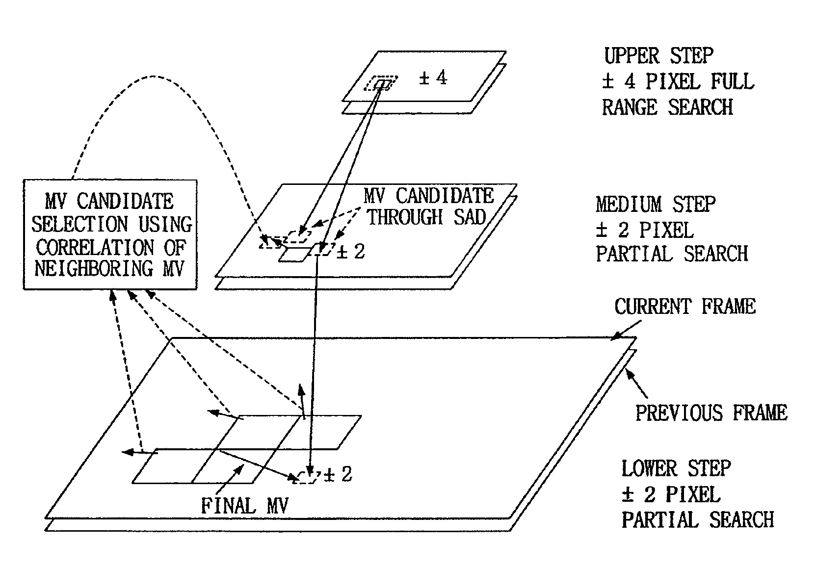
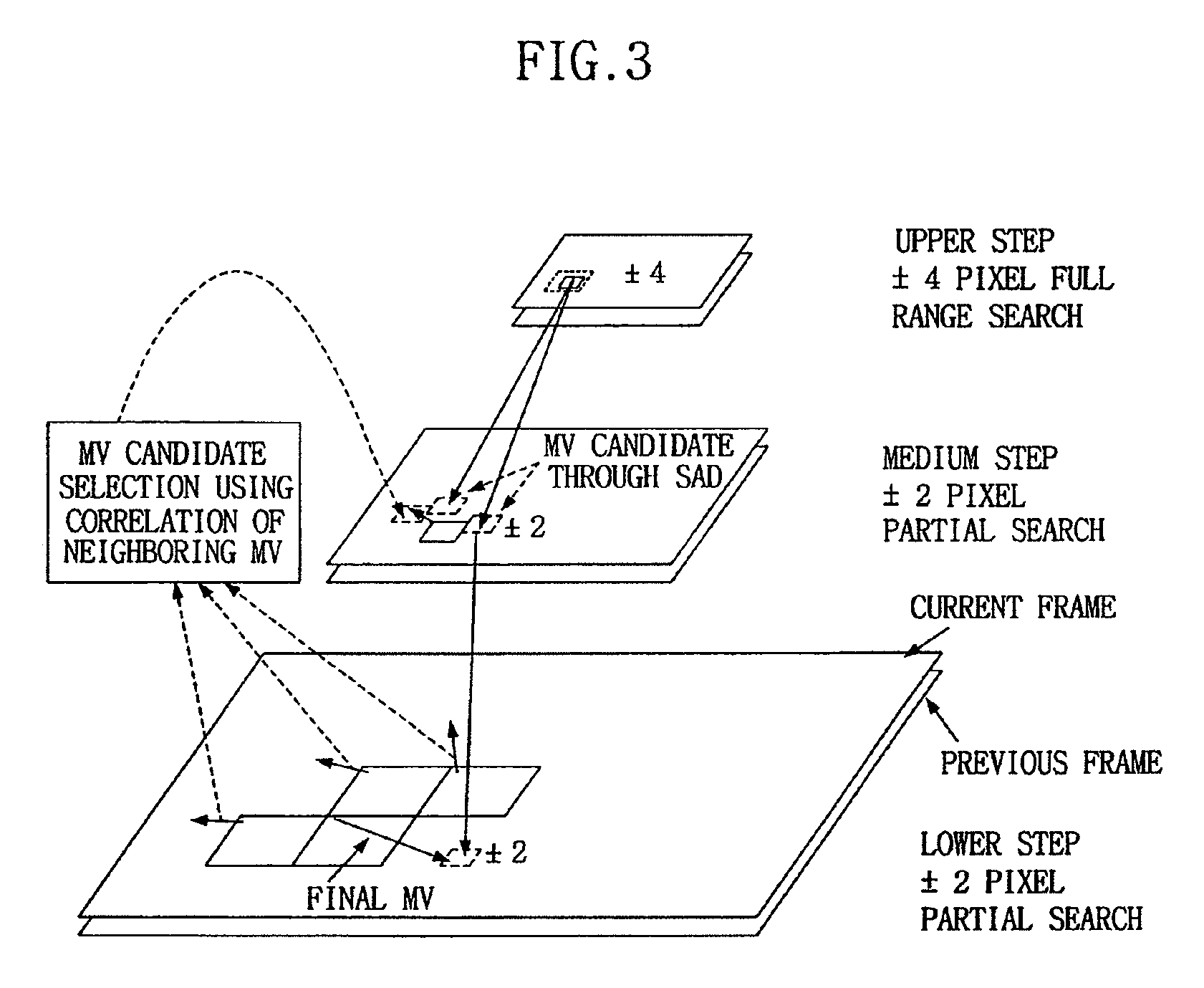
[0036]A multi-resolution search using multiple candidates and spatial correlation of motion field (MRMCS) uses numerous motion vector candidates as the basis of a hierarchical search block matching algorithm (HSBMA), and also is an algorithm to increase efficiency by using a candidate obtained by using a spatial correlation. A basic idea of the spatial correlation algorithm is the presumption that a motion vector of a block representing part of a moving physical object is similar to a motion vector of spatially neighboring blocks (of the same physical object). A method of deciding a ...


PUM


Abstract

A motion estimator and an estimation method for a video encoder to reduce power consumption by reducing the computational complexity of the motion estimator. In an upper step, a full search for a ±4 pixel search region for a 4×4 pixel block is performed at ¼ video resolution, to detect two motion vector candidates. In a medium step, a partial search for two vector candidates selected in the upper step and one vector candidate using a spatial correlation is performed for a 8×8 block within a ±1 or ±2 search region, to decide one motion vector candidate. In a lower step, a partial search for the ±1 or ±2 search region on 16×16 block is performed at full resolution, and a half pixel search for a motion vector candidate obtained in the lower step is performed to estimate a final motion vector. A ±4 pixel search region is operatively divided into four search regions, and the estimator sequentially searches the four ±2 pixel search regions to sequentially output SAD values.

Description

CROSS-REFERENCE TO RELATED APPLICATION[0001]This application is a divisional of application Ser. No. 10 / 730,237 filed Dec. 8, 2003, now U.S. Pat. No. 7,362,808 which claims foreign priority under 35 U.S.C. § 119 to Korean Patent Application No. 2002-77743, filed on Dec. 9, 2002, in the Korean Intellectual Property Office, the disclosure of which is incorporated by reference herein in its entirety.TECHNICAL FIELD[0002]The present invention relates to video compression, and more particularly, to method and apparatus for the computationally efficient estimation of movement in video signals.BACKGROUND[0003]When video data is transmitted in real-time, it is desirable to send as little data as possible. Data-reducing, coding / decoding of digital video signals is, in many cases, based on a motion-compensated interpolation of picture element values (interframe coding). For this purpose, movement vectors or displacement vectors are required for picture element (pixel) blocks. These movement v...

Claims


Application Information

Patent Timeline
Patent Type & Authority Patents(United States)
IPC IPC(8): H04N7/12H04N7/32H04B1/66H04N7/26H04N11/02H04N11/04
CPCH04N19/53H04N19/156H04N19/51
Inventor KANG, JUNG-SUN
Owner SAMSUNG ELECTRONICS CO LTD
Why Eureka
Try Eureka