Super-regenerative microwave detector

a detector and super-regenerative technology, applied in the field of microwave detectors, can solve the problems of low noise, low efficiency, and low loss of amplifier components at 500 ghz, and achieve the effect of reducing noise, reducing loss, and reducing nois

Inactive Publication Date: 2009-09-15
RAYTHEON CO
View PDF24 Cites 17 Cited by
  • Summary
  • Abstract
  • Description
  • Claims
  • Application Information

AI Technical Summary

Problems solved by technology

Schottky detectors can operate directly at deep millimeter-wavelengths (>500 GHz), but they are very lossy and have noise figures on the order of 12 dB at 500 GHz.
However, this amplifier component not easily provided by transistor technology due to the extreme frequencies involved.
So, previous detectors have either high loss or require complicated RF circuitry to efficiently detect millimeter-wave signals.

Method used


Image

  • Super-regenerative microwave detector
  • Super-regenerative microwave detector
  • Super-regenerative microwave detector

Examples


Embodiment Construction

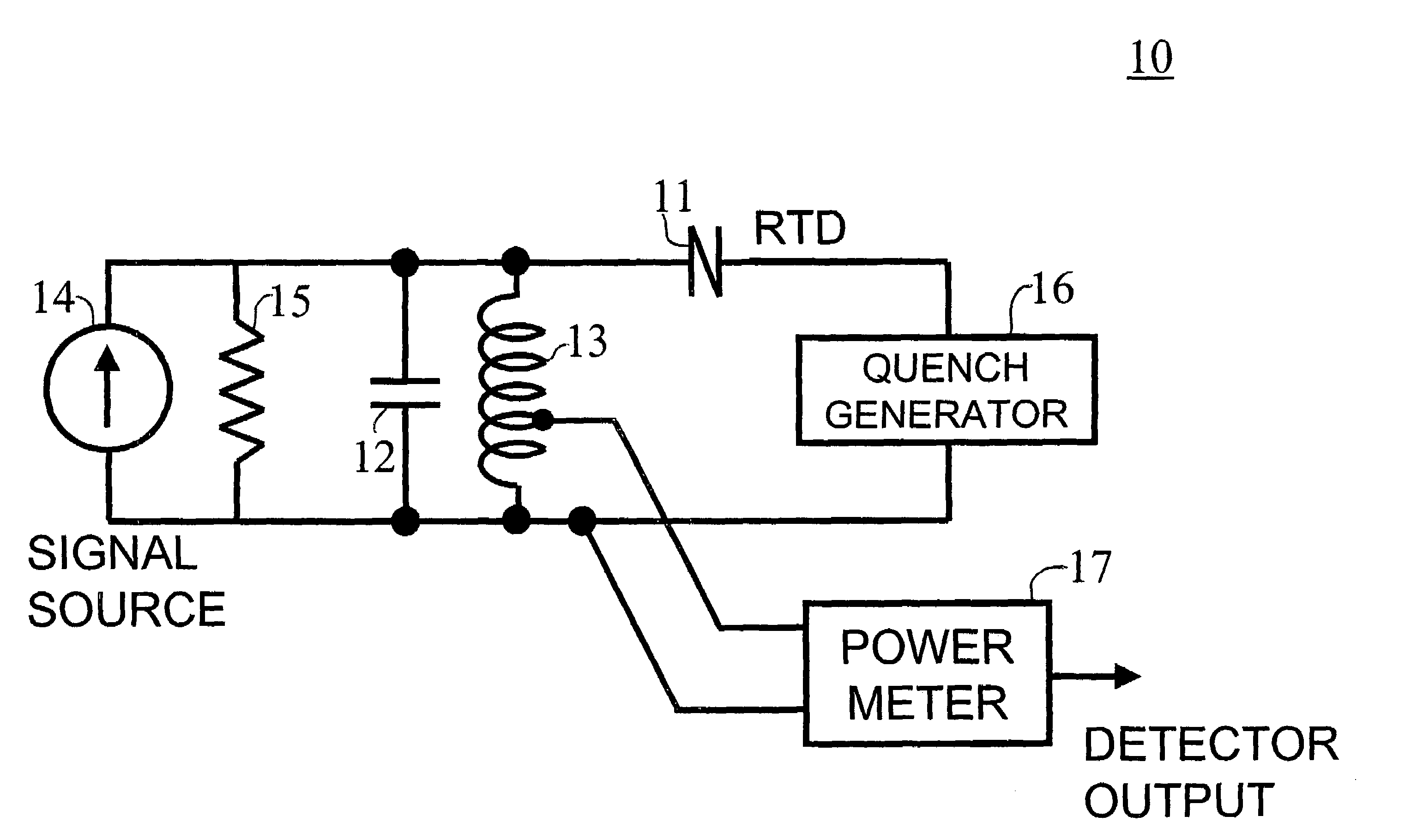
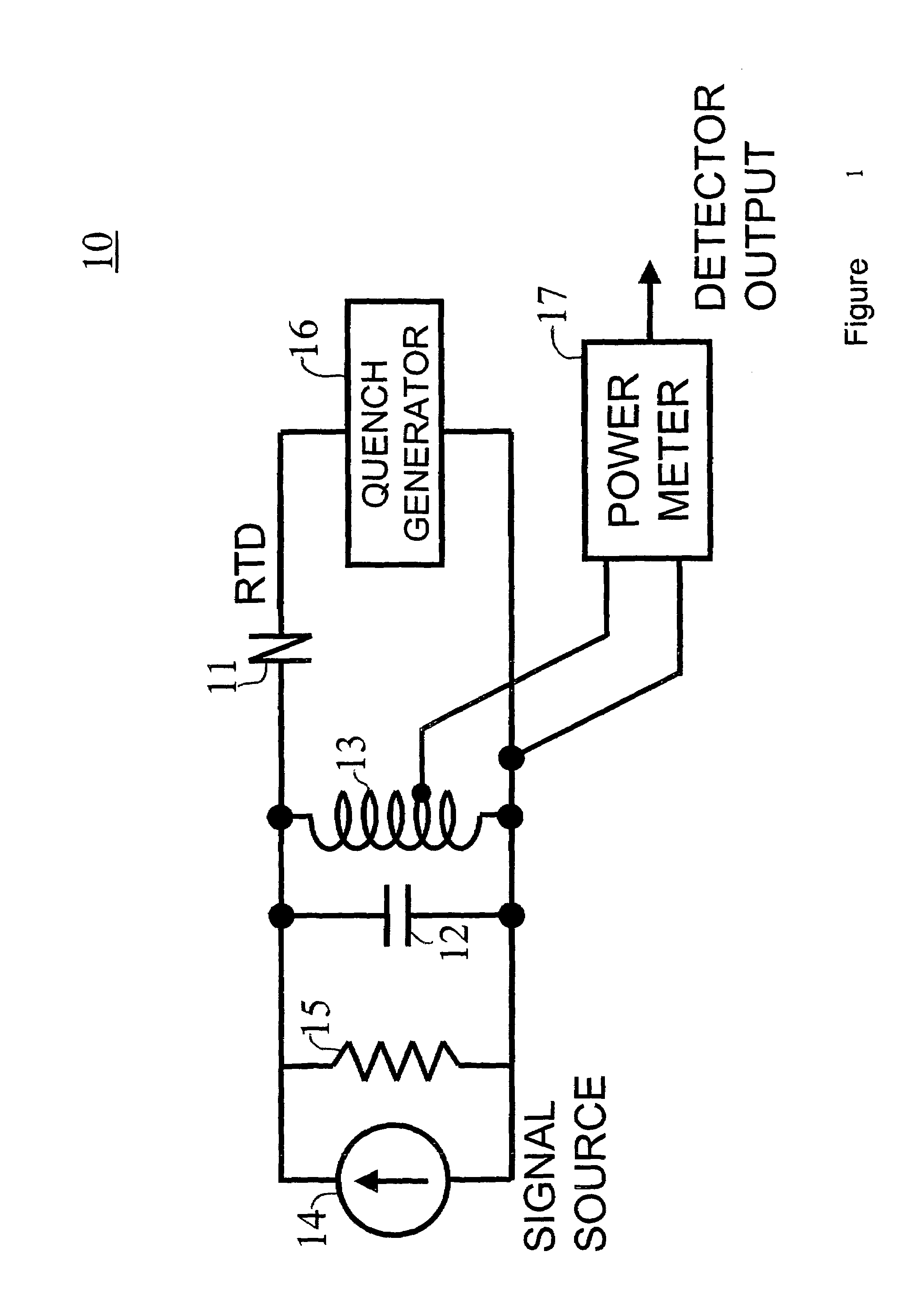
[0027]When power is applied to any electronic oscillator, steady state oscillations build up from random noise fluctuations within the circuit. The turn-on delay, the time between power-up and stable oscillation, is controlled by the overall gain, feedback, and noise level within the circuit. This characteristic turn-on time can be shortened by injecting a coherent, resonant signal into the oscillator. The circuit gain amplifies the injected signal, feeding back the amplified wave until stable oscillation is achieved. The final amplitude of the oscillations may be a million times greater than the strength of the injected input signal. This effect, called super-regeneration, can be used to build simple, highly sensitive radio frequency detectors using resonant tunneling devices. Due to their high intrinsic speed, super-regenerative detectors based on resonant tunneling devices can operate well above 1000 GHz. FIG. 1 shows a schematic of a conceptual super-regenerative millimeter-wave...


PUM


Abstract

A resonant tunneling diode or diode array oscillator (10) including a resonant diode (11) is coupled to a millimeter-wave source (14) and a quench generator (16) for periodically quenching the oscillations so that the average oscillation time of the oscillator is proportional to signal strength of the source (14). The signal source can be from an antenna such as a dipole or tapered slot line antenna.

Description

RELATED APPLICATIONS[0001]This application is a divisional of U.S. application Ser. No. 09 / 716,417, filed Nov. 21, 2000, entitled “Super-Regenerative Microwave Detector,” now U.S. Pat. No. 6,993,315.TECHNICAL FIELD OF THE INVENTION[0002]This invention relates to microwave detectors and more particularly to a very sensitive detector of millimeter wavelength (millimeter-wave) RF signals and sub-millimeter wavelength (sub-millimeter-wave) RF signals.BACKGROUND OF THE INVENTION[0003]Microwave detectors are essential microwave components. They convert RF energy into electrical form for analysis. The subject detector can be used anywhere high sensitivity is required in a simple detector. Obvious applications include simple sub-millimeter-wave imagers, phased array receivers, proximity detecting warhead fuses, and communication links. Since the detector is an oscillator, it can be configured as a transmitter and a receiver in the same circuit. This permits its use in simple wideband commun...

Claims


Application Information

Patent Timeline
Patent Type & Authority Patents(United States)
IPC IPC(8): H04B1/16H03B7/08
CPCB82Y10/00H03B7/08G01R21/12B82Y30/00
Inventor FRAZIER, GARY
Owner RAYTHEON CO
Why Eureka
Try Eureka