Eureka AIR delivers breakthrough ideas for toughest innovation challenges, trusted by R&D personnel around the world.

Elongated stopper device

Inactive Publication Date: 2009-10-06
REFRACTORY INTELLECTUAL PRORERTY GMBH & CO KG
View PDF16 Cites 0 Cited by
  • Summary
  • Abstract
  • Description
  • Claims
  • Application Information

AI Technical Summary

Benefits of technology

[0011]It is therefore an object of the present invention to provide an elongated stopper device for flow control of a molten metal from a vessel, containing molten metal, which is easy to produce and provides effective sealing means.
[0013]Contrary to the known sealing technique it has been discovered that the desired tightness may be improved characteristically when the sealing member is compressed by forces effective in different directions, for example by introduction of a radial force additionally to any axial forces. The more the sealing material is compressed by radial forces the more effective is the sealing. The sealing and corresponding tightness may be achieved during a complete working period of the stopper device, i.e. at ambient temperature, during heat up, at maximum working temperature and during cooling down.
[0026]Even during service the new design develops further advantages. During service (under high temperature load) differential expansion arising from the increased temperature results in a more radial expansion of the metallic support rod than of the ceramic body surrounding it and therefore in an increase in the seal efficiency by further compression of the sealing element in radial direction.
[0041]Said graphite sealing member (gasket) may be used at service temperatures of typically 800-1.200° Celsius without problems. There is no change in rigidity or sintering at these temperatures with such graphite gaskets. On the other hand even at these temperatures the sealing member retains the ability for further deformation to both enhance the efficiency of the sealing mechanism and absorb mechanical stresses which could otherwise result in mechanical damage during service.
[0042]The compressed sealing member exhibits these desired properties. The absence of a supply of oxygen within the assembly and the inert atmosphere provided by gas injection through an axial bore of said rod and / or the bore hole of the ceramic body prevent any degradation by oxidation during service.

Problems solved by technology

It has now been found that the disadvantages described mostly result, when the sealing means is more or less exclusively compressed between like surfaces by unidirectional axial forces.

Method used


Image

  • Elongated stopper device
  • Elongated stopper device
  • Elongated stopper device

Examples


Embodiment Construction

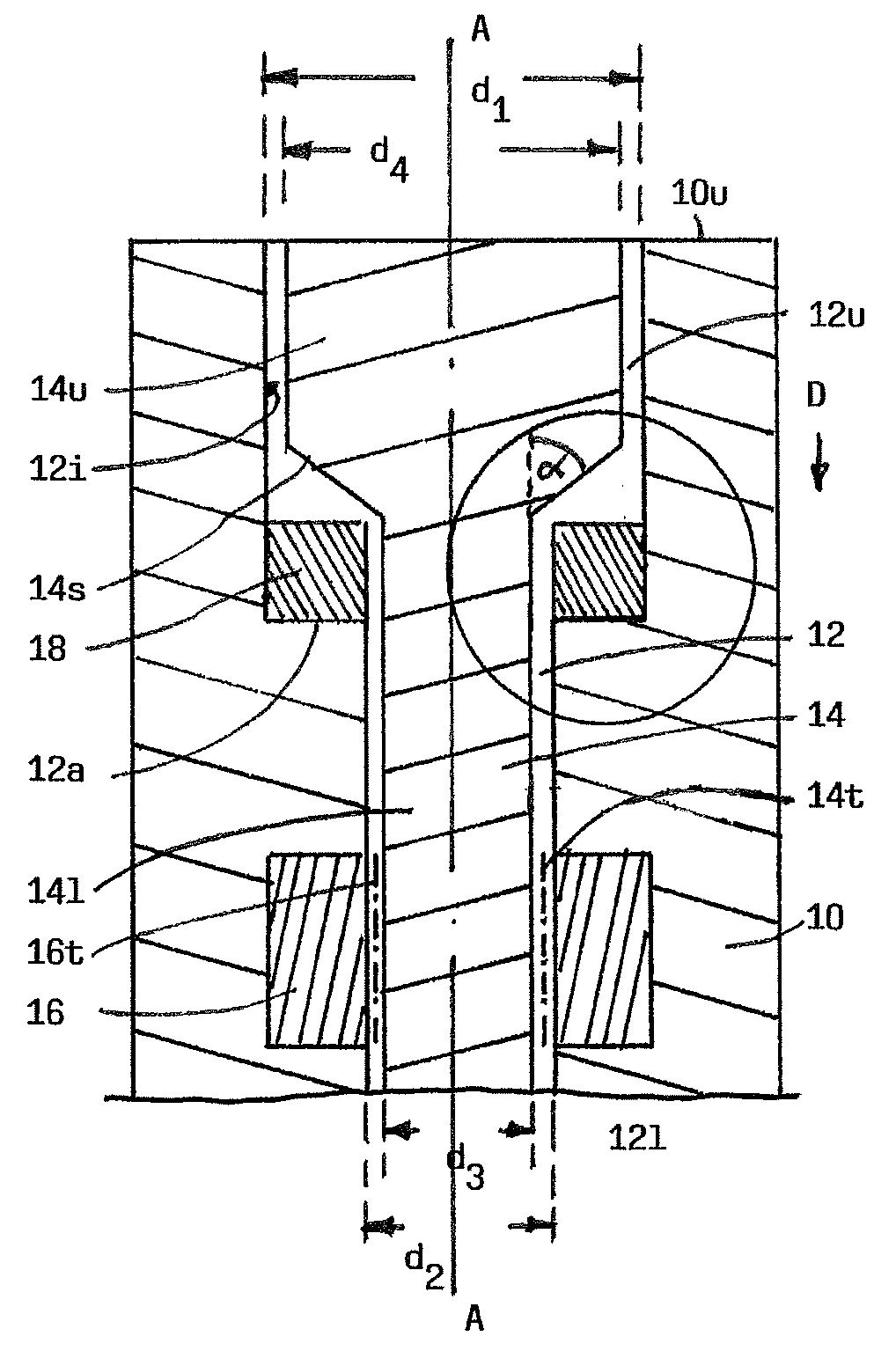
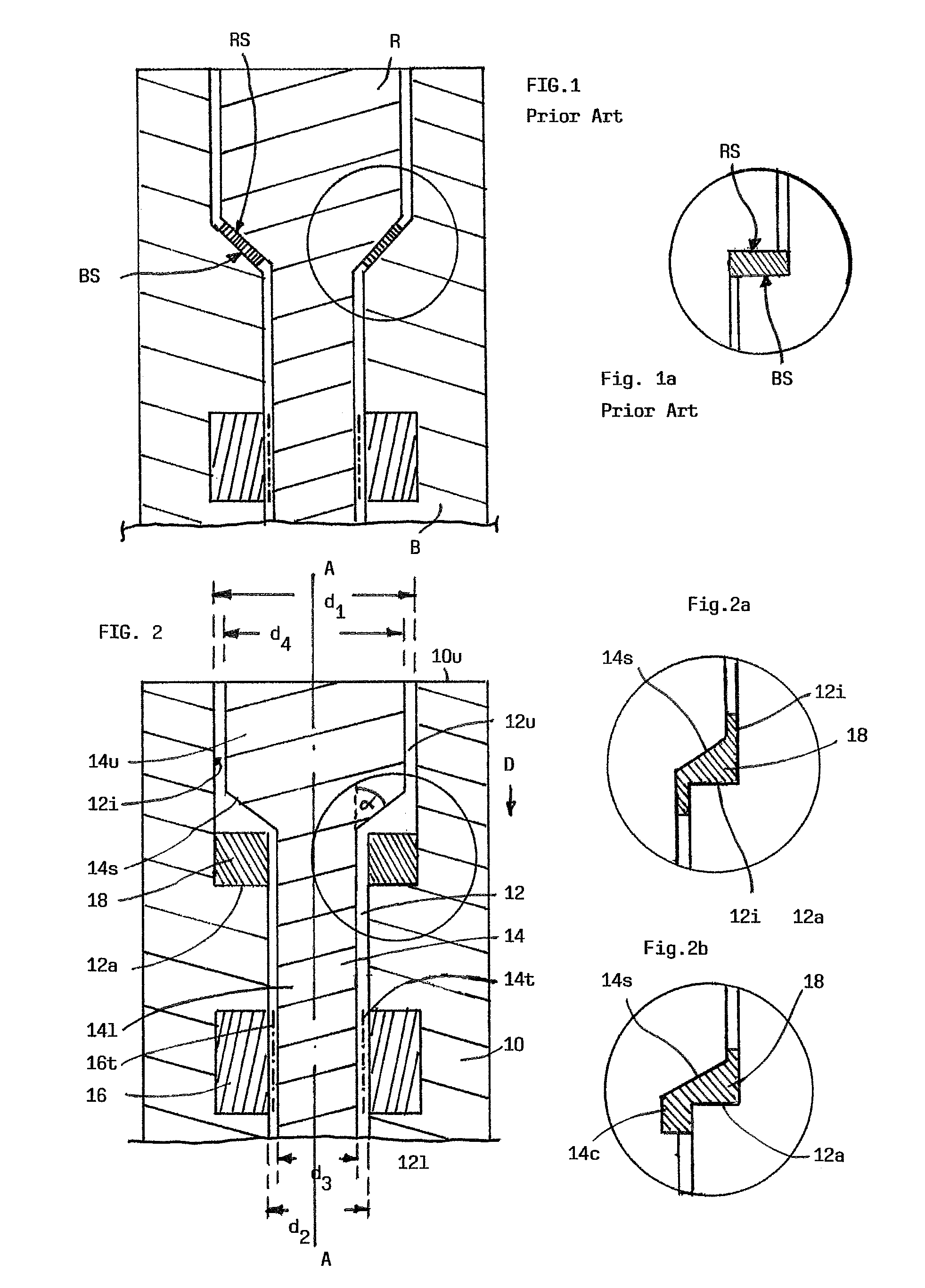
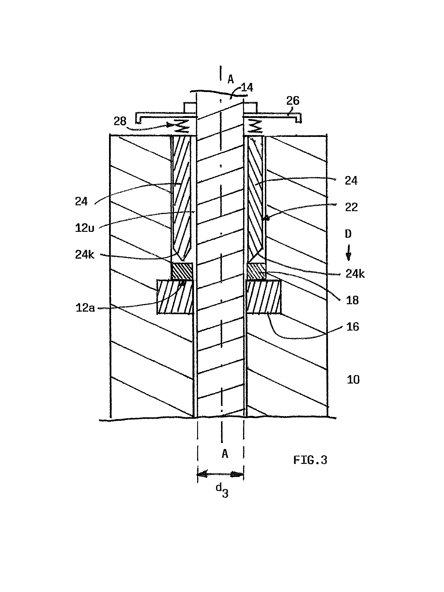
[0053]The stopper device comprises an elongated refractory body 10 with a central bore hole 12, positioned coaxially with respect to body 10 and adapted to fixedly receive a metal rod 14 for its attachment to a (non-shown) lifting mechanism.

[0054]The bore hole 12 is of more or less cylindrical shape. It has an upper part 12u, characterised by a diameter d1 and a lower part 12l characterised by a smaller diameter d2.

[0055]A transition section between upper part 12u and lower part 12l is provided by an annular surface 12a, onto which a ring-shaped graphite gasket 18 is placed. This gasket 18 is made of a graphite foil, coiled up to said ring-shape shown in FIG. 2.

[0056]Below said gasket 18 a ceramic thread 16 with an inner thread 16t is arranged within the ceramic refractory material of body 10 as to threadably receive a corresponding outer thread 14t of rod 14.

[0057]Rod 14 is designed as follows: Its lower part 14l, provided with said outer thread 14t, has a diameter d3, slightly sma...


PUM

PropertyMeasurementUnit
Massaaaaaaaaaa
Massaaaaaaaaaa
Volumeaaaaaaaaaa

Abstract

An enlongated stopper device for flow-control of molten metal from a vessel, containing molten metal, said device comprising: a) a body (10) made of a refractory ceramic material, b) a bore hole (12), having a longitudinal axis (A) and extending from an upper surface (10u) of said body downwardly, c) a rod (14), penetrating with one end (14l) into said bore hole (12) and being fixedly secured within said body (10), d) a sealing member (18), being arranged within a space adjacent to or being part of said bore hole (12), said space being defined at least partly by unlike surface sections (12a, 12i, 14s) of said rod (14) and said body (10) respectively.

Description

FIELD OF THE INVENTION[0001]The invention relates to an elongated stopper device for flow control of molten metal, i.e. for controlling the flow of molten metal from a metallurgical vessel, such as a tundish.BACKGROUND OF THE INVENTION[0002]It is well known in steel casting to employ a one-piece refractory stopper rod, which is moved vertically by the use of a lifting mechanism in order to vary the cross-sectional area of an outlet opening of the corresponding metallurgical vessel.[0003]Those stopper rods have also been used to introduce an inert gas, such as argon, into the molten steel for removing non-metallic inclusions from the molten metal.[0004]In all cases the stopper device must withstand hours submerged in molten metal. It must also be capable of enduring the harsh thermal shock encountered on the start-up of casting and any mechanical forces imposed to it.[0005]Insofar many attempts have been made to improve the mechanical and thermal properties of such a stopper device a...

Claims


Application Information

Patent Timeline
IPC IPC(8): B22D41/18
CPCB22D41/186B22D41/18
Inventor LEE, STEPHEN
Owner REFRACTORY INTELLECTUAL PRORERTY GMBH & CO KG
Why Eureka
Eureka Blog
Learn More