Folded antenna

a folding antenna and antenna body technology, applied in the direction of elongated active element feed, resonant antenna, radiating element structure, etc., can solve the problems of difficult adjustment of impedances for both frequencies of two or more resonance frequency bands, inability to achieve down sizing of devices, etc., to achieve small influence on the input impedance of antennas, increase in length, and small capacitance

Inactive Publication Date: 2009-10-06
YOKOWO CO LTD +1
View PDF10 Cites 16 Cited by
  • Summary
  • Abstract
  • Description
  • Claims
  • Application Information

AI Technical Summary

Benefits of technology

[0016]The structure according to the present invention gives a small influence to an input impedance of the antenna because of a small capacitance between the ground plate and the antenna element, since the segments of the antenna element are short near the ground plate, and increase in length as the segments are away from the ground plate. And as explained later, since a resonance frequency can be adjusted by changing the lengths of the segments in order, a low frequency band can be set closely to a desired frequency, and, simultaneously, two resonance frequencies in high frequency can also be set very near, and the range between two resonance frequencies can be treated as one resonance in a high frequency band.
[0017]As a result, the impedance can be prevented from lowering related to the ground plate, and an antenna which resonates at a desired frequency band with a desired bandwidth can be realized. Moreover, there can be obtained an antenna which transmits and receives signals of two frequency bands with wide bandwidths by a single antenna at high frequency bands apart from each other, for example, from 2.4 to 2.5 GHz and from 5 to 6 GHz employed in present LANs.

Problems solved by technology

Thus, there occurs problems that down sizing of device can not be achieved and that adjusting impedances for both frequencies of two or more resonance frequency bands is difficult in case of the small distance h.

Method used


Image

  • Folded antenna
  • Folded antenna
  • Folded antenna

Examples


Embodiment Construction

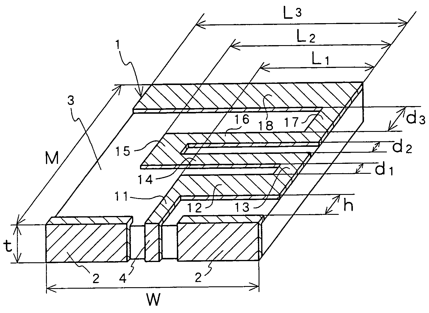
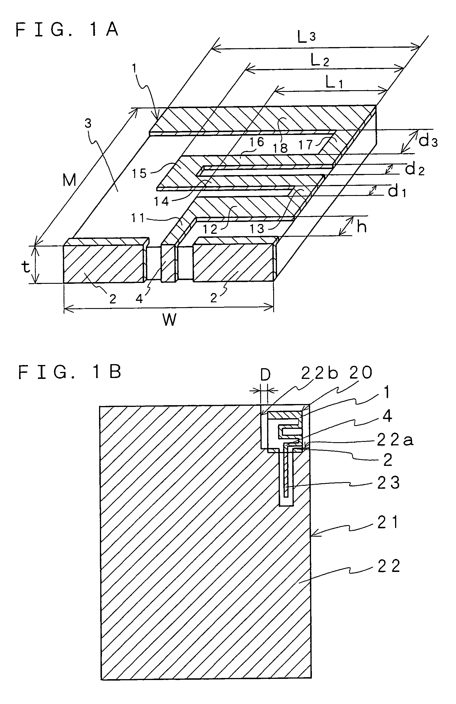
[0032]A description will be given below of a folded antenna according to the present invention in reference to the drawings. As shown in an explanatory perspective view of an embodiment in FIG. 1A, the folded antenna according to the present invention includes a ground plate 2 and an antenna element 1 having a plurality of turning parts 13, 15, 17 and a plurality of segments (a first segment 12, a set of a second segment 14 and a third segment 16, and a forth segment 18) formed between the turning parts. The segments are formed by turning back the antenna element in zigzag in parallel to one face of the ground plate 2 at the turning parts, while the antenna element generally extending perpendicularly to the one face of the ground plate 2. A length of one segment or a length of a set of segments, which is a pair of arbitrary two adjacent segments having the same length, is shorter on a side of the one face of the ground plate 2 (feeding part 4) and increase gradually as the segment o...


PUM


Abstract

An antenna element 1 is formed such that a plurality of turning parts 13, 15, 17 are formed by being turned back in zigzag in parallel to a ground conductor film 2 while extending perpendicularly thereto and the lengths of segments 12, 14, 16, 18 between the turning parts are shorter on a side of the ground conductor film 2 (a side of a feeding part 4) and increase gradually as the segments are away from the ground conductor film 2. The turning parts of the antenna element 1 are formed such that the antenna resonates at two or more frequency bands, and has a fractional bandwidth of 4% or more of its frequency in a first frequency band and a fractional bandwidth of 15% or more of its frequency in a second frequency band by adjusting the lengths L1, L2 and L3 of respective segments and the intervals d1, d2 and d3 between adjacent segments. Consequently, a wideband antenna is realized in two or more multi-frequency bands, for example 2.4 to 2.5 GHz and 5 to 6 GHz, by using a single folded antenna.

Description

FIELD OF THE INVENTION[0001]The present invention relates to an antenna suitable for use in, for example, wireless LANs (Local Area Networks) or the like, which can transmit and receive signals of two or more frequency bands, each of which has a wide bandwidth, a small size and a high function. More particularly, the present invention relates to a small-sized antenna which can operate at two frequency bands of, for example, 2.4 GHz and 5 GHz, and which still has a bandwidth of approximately 1 GHz at the frequency band of 5 GHz.BACKGROUND OF THE INVENTION[0002]In the prior art, a folded antenna 50, for example, shown in FIG. 10 has been introduced as an antenna suitable for transmitting and receiving signals of two or more frequency bands having approximately two times relationship (for example, cf. PATENT DOCUMENT 1). In the folded antenna 50, it is known that resonance at two or more frequency bands having approximately two times relationship can be achieved, since resonance freque...

Claims


Application Information

Patent Timeline
Patent Type & Authority Patents(United States)
IPC IPC(8): H01Q9/16H01Q1/38H01Q1/36H01Q5/10H01Q9/38H01Q9/42
CPCH01Q1/2283H01Q1/36H01Q1/38H01Q5/357H01Q9/42H01Q13/206H01Q5/00
Inventor GE, JUNXIANGKAMEDA, SHOZABUROICHIKAWA, HIROSHI
Owner YOKOWO CO LTD
Why Eureka
Try Eureka