Position measurement system and lithographic apparatus

a technology of position measurement and lithographic apparatus, which is applied in the direction of electrical equipment, instruments, printers, etc., can solve the problems of increased measurement error of the second sensor, limited operation range of the measurement system, and inability to accurately measure the position of the sensor, so as to achieve the effect of improving the accuracy of the position measurement system

Active Publication Date: 2009-10-06
ASML NETHERLANDS BV
View PDF10 Cites 4 Cited by
  • Summary
  • Abstract
  • Description
  • Claims
  • Application Information

AI Technical Summary

Benefits of technology

[0008]Embodiments of the invention include an improved position measurement system. In embodiments of the invention, the accuracy of the position measurement system is improved during a take over process between two sensors of the measurement system.

Problems solved by technology

Because of the limited size of, e.g., the mirror or the grating, the operating range of the measurement system may be limited.
In such a multi-sensor measurement system, problems may arise during the transition of the position measurement by a first sensor to the position measurement by a second sensor.
Because this initialization is based upon measurements of both the first sensor and the second sensor, measurements that may contain a measurement error, this initialization may result in an increased measurement error for the second sensor.
During a next transition (either a transition of a measurement by the second sensor to a measurement by a third sensor or a transition of a measurement by the second sensor to a measurement by the first sensor) a further increase in the measurement error may occur.
As such, the accuracy of a multi-sensor measurement system used in a conventional way may deteriorate due to transition from a measurement by one sensor to a measurement by another sensor.

Method used


Image

  • Position measurement system and lithographic apparatus
  • Position measurement system and lithographic apparatus
  • Position measurement system and lithographic apparatus

Examples


Embodiment Construction

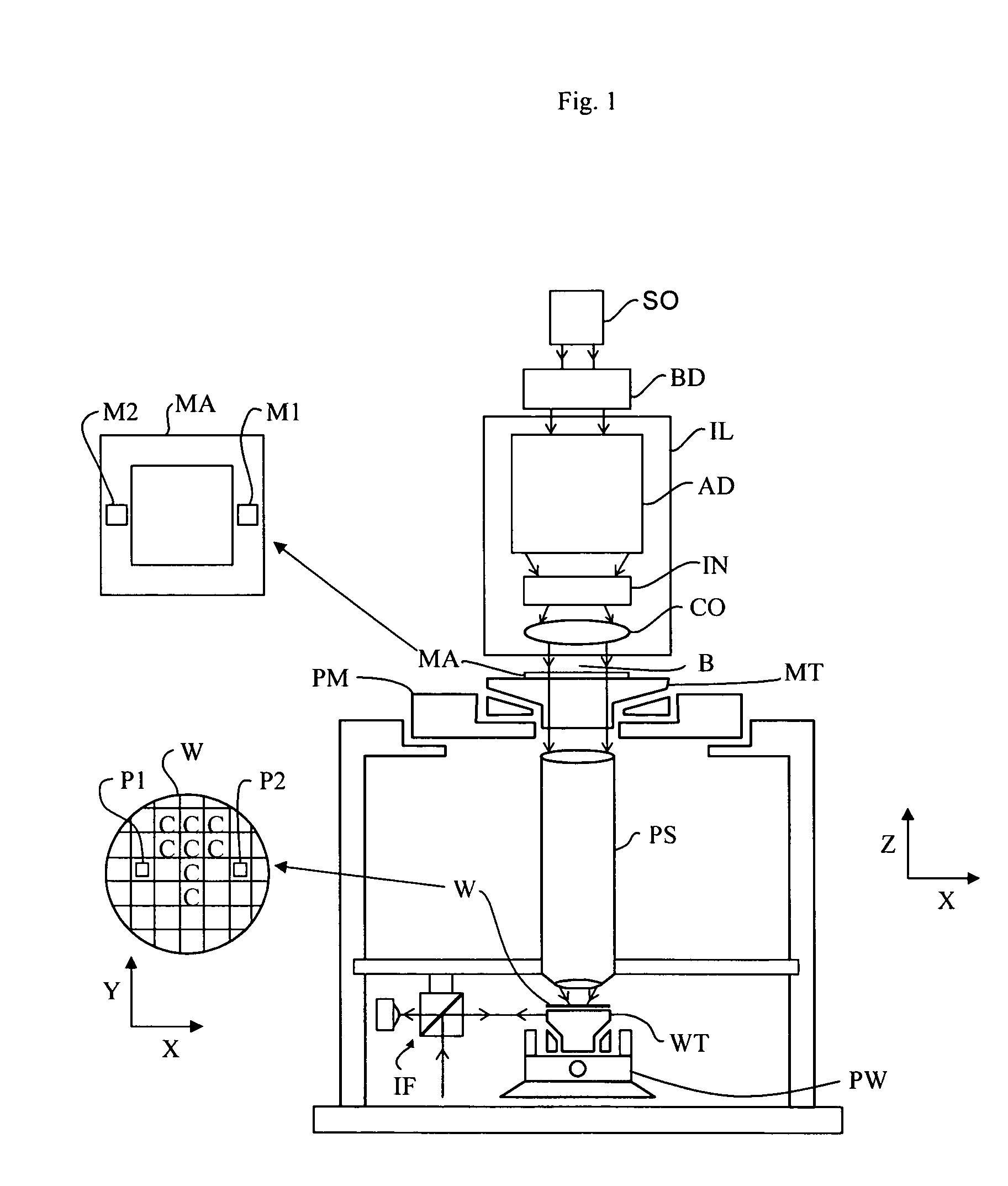
[0023]FIG. 1 schematically depicts a lithographic apparatus according to one embodiment of the invention. The apparatus includes an illumination system (illuminator) IL configured to condition a radiation beam B (e.g., UV radiation or EUV radiation); a support structure (e.g., a mask table) MT constructed to support a patterning device (e.g., a mask) MA and connected to a first positioner PM configured to accurately position the patterning device in accordance with certain parameters; a substrate table (e.g., a wafer table) WT constructed to hold a substrate (e.g., a resist-coated wafer) W and connected to a second positioner PW configured to accurately position the substrate in accordance with certain parameters; and a projection system (e.g., a refractive projection lens system) PS configured to project a pattern imparted to the radiation beam B by patterning device MA onto a target portion C (e.g., including one or more dies) of the substrate W.

[0024]The illumination system may i...


PUM


Abstract

A position measurement system includes a first position measurement unit configured to measure a position of an object in a first and a second direction, the first position measurement unit including a first sensor and a first grating that extends in a first direction, a second position measurement unit configured to measure the position of the object in the first and the second direction, the second position measurement unit including a second sensor and a second grating that extends in the first direction. The position measurement system is configured to initialize the second position measurement unit based on a position measurement of the first position measurement unit.

Description

CROSS-REFERENCE TO RELATED APPLICATIONS[0001]This is a Continuation-In-Part Application of U.S. patent application Ser. No. 11 / 217,670, filed on Sep. 2, 2005, now U.S. Pat. No. 7,348,574 the entire content of which is incorporated herein by reference.BACKGROUND[0002]1. Field of the Invention The present invention relates to a position measurement system and a lithographic apparatus.[0003]2. Description of the Related Art[0004]A lithographic apparatus is a machine that applies a desired pattern onto a substrate, usually onto a target portion of the substrate. A lithographic apparatus can be used, for example, in the manufacture of integrated circuits (ICs). In that instance, a patterning device, which is alternatively referred to as a mask or a reticle, may be used to generate a circuit pattern to be formed on an individual layer of the IC. This pattern can be transferred onto a target portion (e.g., including part of, one, or several dies) on a substrate (e.g., a silicon wafer). Tra...

Claims


Application Information

Patent Timeline
Patent Type & Authority Patents(United States)
IPC IPC(8): G03B27/42G03B27/52
CPCG03F7/70775G03F7/70008G03F7/70216G03F7/70716H01L21/67259
Inventor PRIL, WOUTER ONNOEUSSEN, EMIEL JOZEF MELANIEVAN DER PASCH, ENGELBERTUS ANTONIUS FRANSISCUS
Owner ASML NETHERLANDS BV
Why Eureka
Try Eureka