
Power circuit for generating non-isolated low voltage power in a standby condition

a power circuit and standby condition technology, applied in the direction of electric variable regulation, process and machine control, instruments, etc., can solve the problems of high standby high power consumption of electronic devices, so as to reduce the voltage and reduce the voltage

Active Publication Date: 2009-10-13
NAT SEMICON CORP
View PDF17 Cites 59 Cited by
  • Summary
  • Abstract
  • Description
  • Claims
  • Application Information

AI Technical Summary

Benefits of technology

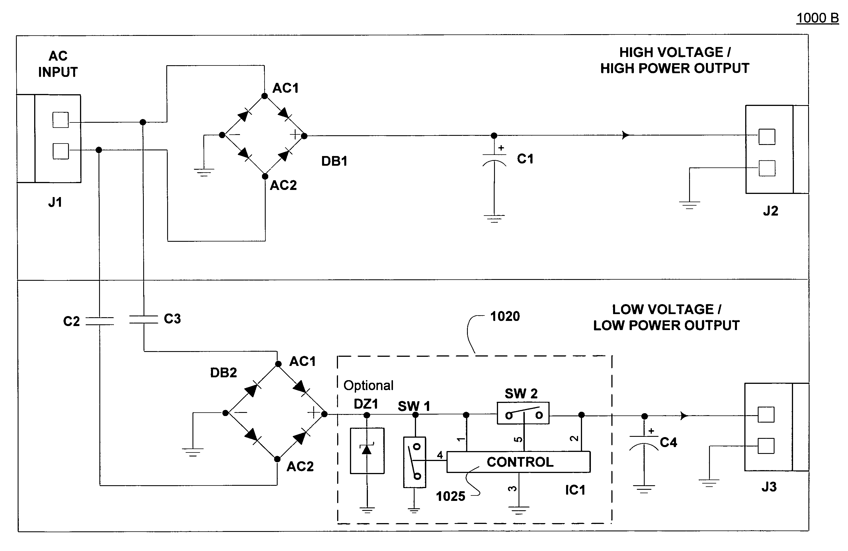
[0020]Specifically, in one embodiment, a power circuit is described that generates a non-isolating low voltage power supply using an AC voltage drop in standby. The power circuit includes an AC connector that generates a first AC input and a second AC input that are opposite in phase. The power circuit also includes a first diode bridge rectifier circuit coupled at separate nodes to the first AC input, the second AC input, and a ground. The first diode bridge rectifier circuit at a first output node provides a high voltage power signal to a load. In addition, the power circuit also includes a second diode bridge rectifier circuit coupled at separate nodes to the first AC input, the second AC input, and the ground. The second diode rectifier at a second output node provides a low voltage power signal to a microcontroller. The power circuit also includes first and second capacitors. The first capacitor is coupled in series with the first AC input and a first node of the second diode bridge rectifier circuit and reduces a voltage of the first AC input. The second capacitor is coupled in series with the second AC input and a second node of the second diode bridge rectifier circuit and drops a voltage of the second AC input.

Problems solved by technology

Unfortunately, the standby energy consumption of the electronic device may be as high as ten percent of the total energy consumption of the device, especially when the electronic device spends a majority of its operating lifetime in a standby condition.
As such, the electronic device consumes a significant amount of power just waiting for a control signal when in the standby condition.
This standby power consumption can quickly add up for a particular household, for example, when considering the number of electronic devices that can be in standby condition at one time.
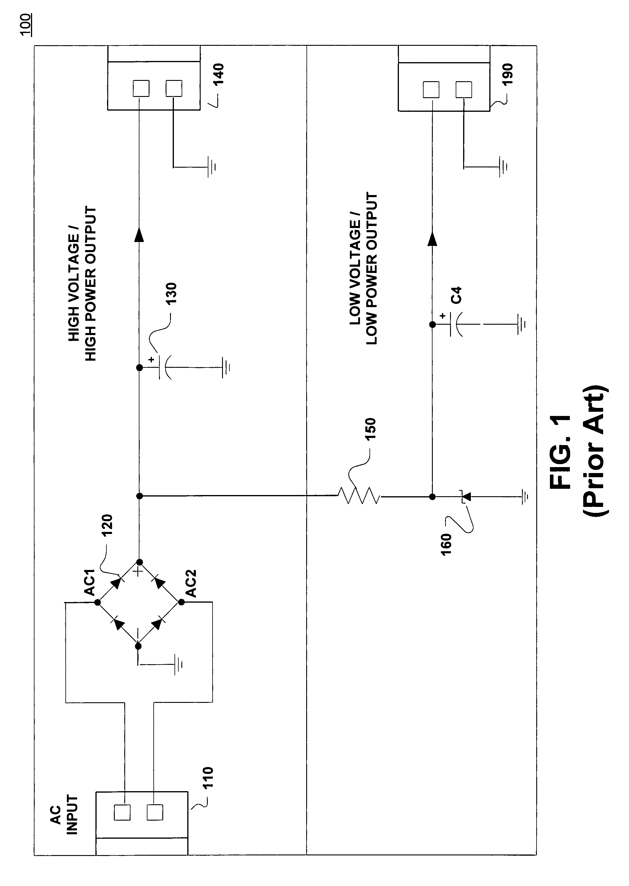
However, the use of a resistor to drop the voltage results in a high power loss through the resistor 150.
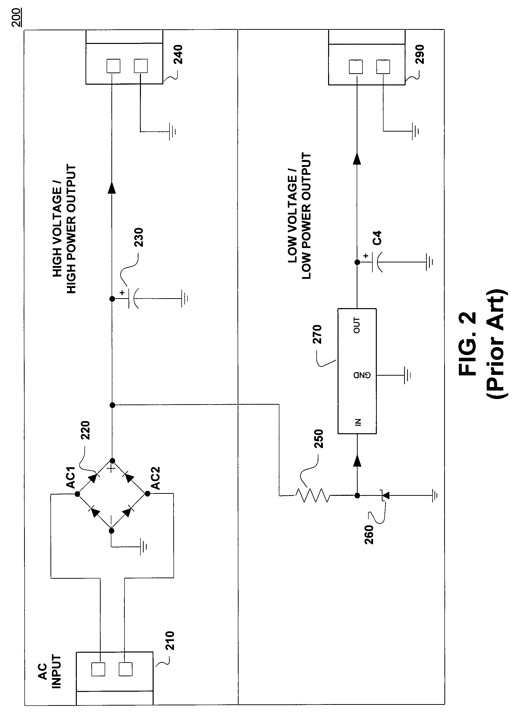
However, the power circuit 200 suffers from the same power consumption inefficiency as the power circuit 100 of Prior Art FIG. 1.
However, the power circuit 300 is more expensive to implement since a step-down transformer 350 is used to lower the voltage down to an acceptable level.
In addition, the use of the step-down transformer 350 is bulky and may unnecessarily increase the size of the power circuit 300.
The use of the auxiliary transformer secondary winding 480 is expensive and bulky, thereby introducing the inefficiencies of the power circuit 300 of FIG. 3.
Unfortunately, the use of a resistor to drop the voltage results in a high power loss through the resistor 475.
In addition, there is a need to control this Darlington circuit during power up and possible brown-outs.
These additional elements further complicate the power supply and render the power circuit 400 too expensive for consumer type applications.

Method used


Image

  • Power circuit for generating non-isolated low voltage power in a standby condition
  • Power circuit for generating non-isolated low voltage power in a standby condition
  • Power circuit for generating non-isolated low voltage power in a standby condition

Examples


Embodiment Construction

[0033]Reference will now be made in detail to the preferred embodiments of the present invention, a power circuit for generating a non-isolated low voltage power supply in standby conditions, examples of which are illustrated in the accompanying drawings.

[0034]Accordingly, various embodiments of the present invention disclose a power circuit that generates a non-isolating low voltage power supply in standby. Embodiments of the present invention are able to generate a low voltage power supply that is significantly lower than 1 watt in tandem with a high voltage output. In many cases, a lower voltage and lower power level output is required in tandem with a high voltage output for a power circuit that provides power to an electronic device. The lower voltage may be required, for example to start-up the switching power supply circuit from a standby condition.

[0035]Embodiments of the present invention can be implemented on any electronic system running in standby mode. The electronic sy...


PUM


Abstract

A power circuit generating a non-isolating low voltage power supply using a capacitive AC voltage drop in standby. Specifically, the power circuit includes an AC connector that generates a first AC input and a second AC input that are opposite in phase. The power circuit also includes first and second diode bridge rectifier circuits that are coupled to the first AC input, the second AC input, and a ground. A first capacitor drops a voltage of the first AC input, and a second capacitor drops a voltage of the second AC input. The first diode bridge rectifier circuit provides a high voltage power signal to a load. The second diode bridge rectifier circuit provides a low voltage power signal to a microcontroller.

Description

BACKGROUND OF THE INVENTION[0001]1. Field of the Invention[0002]Embodiments of the present invention relate to the field of power circuits. More particularly, embodiments of the present invention relate generally to power circuits that generate low voltage power in standby conditions.[0003]2. Related Art[0004]Electronic devices are built to accept control signals even in a standby condition. That is, although the electronic device is turned off, the device is placed in standby condition. From the standby condition, the electronic device consumes power while waiting to accept a control signal that, for example, starts up a switching power supply circuit. The power is consumed by the logic waiting for the control signal, displays (e.g., light emitting diode [LED] monitors), etc.[0005]Unfortunately, the standby energy consumption of the electronic device may be as high as ten percent of the total energy consumption of the device, especially when the electronic device spends a majority ...

Claims


Application Information

Patent Timeline
IPC IPC(8): H02M7/06
CPCH02M3/33523Y02B70/16H02M2001/0032Y02B70/10H02M1/0032H02M7/05
Inventor IACOB, ALIN THEODOR
Owner NAT SEMICON CORP
Learn More