Interferometric synthetic aperture microscopy

a synthetic aperture and interferometer technology, applied in the field of computed imaging methods, can solve the problems of loss of resolution and inconvex transverse direction resolution, and achieve the effect of improving the accuracy of image quality and reducing the cost of image quality

Active Publication Date: 2009-10-13
THE BOARD OF TRUSTEES OF THE UNIV OF ILLINOIS
View PDF3 Cites 52 Cited by
  • Summary
  • Abstract
  • Description
  • Claims
  • Application Information

AI Technical Summary

Problems solved by technology

However, the resolution in the transverse direction is not constant along the beam.
This loss of resolution is usually assumed to be an inevitable consequence of defocus.

Method used


Image

  • Interferometric synthetic aperture microscopy
  • Interferometric synthetic aperture microscopy
  • Interferometric synthetic aperture microscopy

Examples


Embodiment Construction

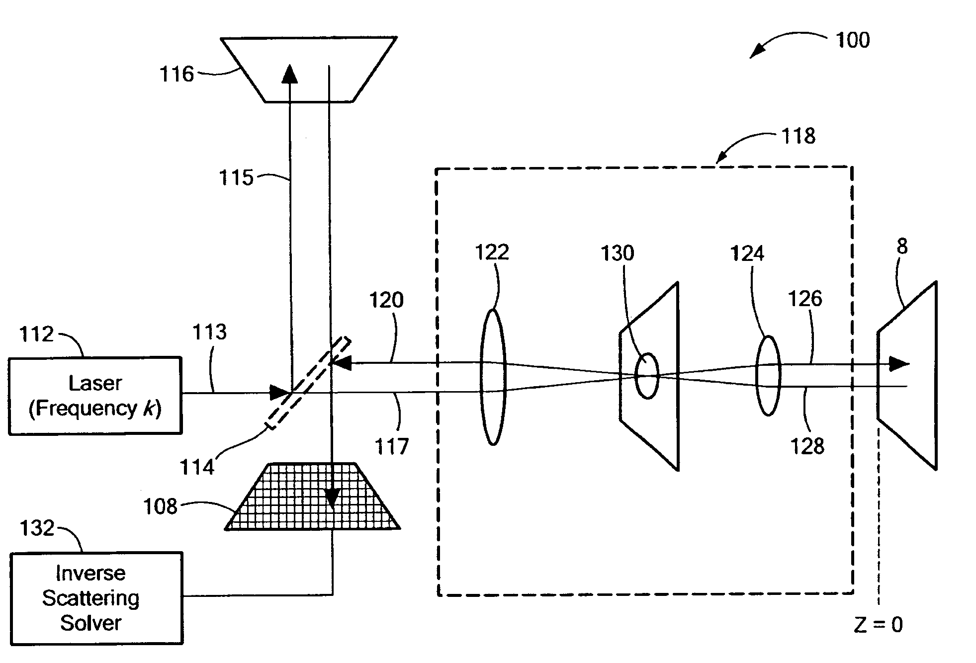
[0036]The following detailed description may be more fully understood by reference to Ralston et al., Inverse Scattering for Optical Coherence Tomography, J. Opt. Soc. Am. A, vol. 23, pp. 1027-37 (May, 2006), which is appended hereto, and incorporated herein by reference.

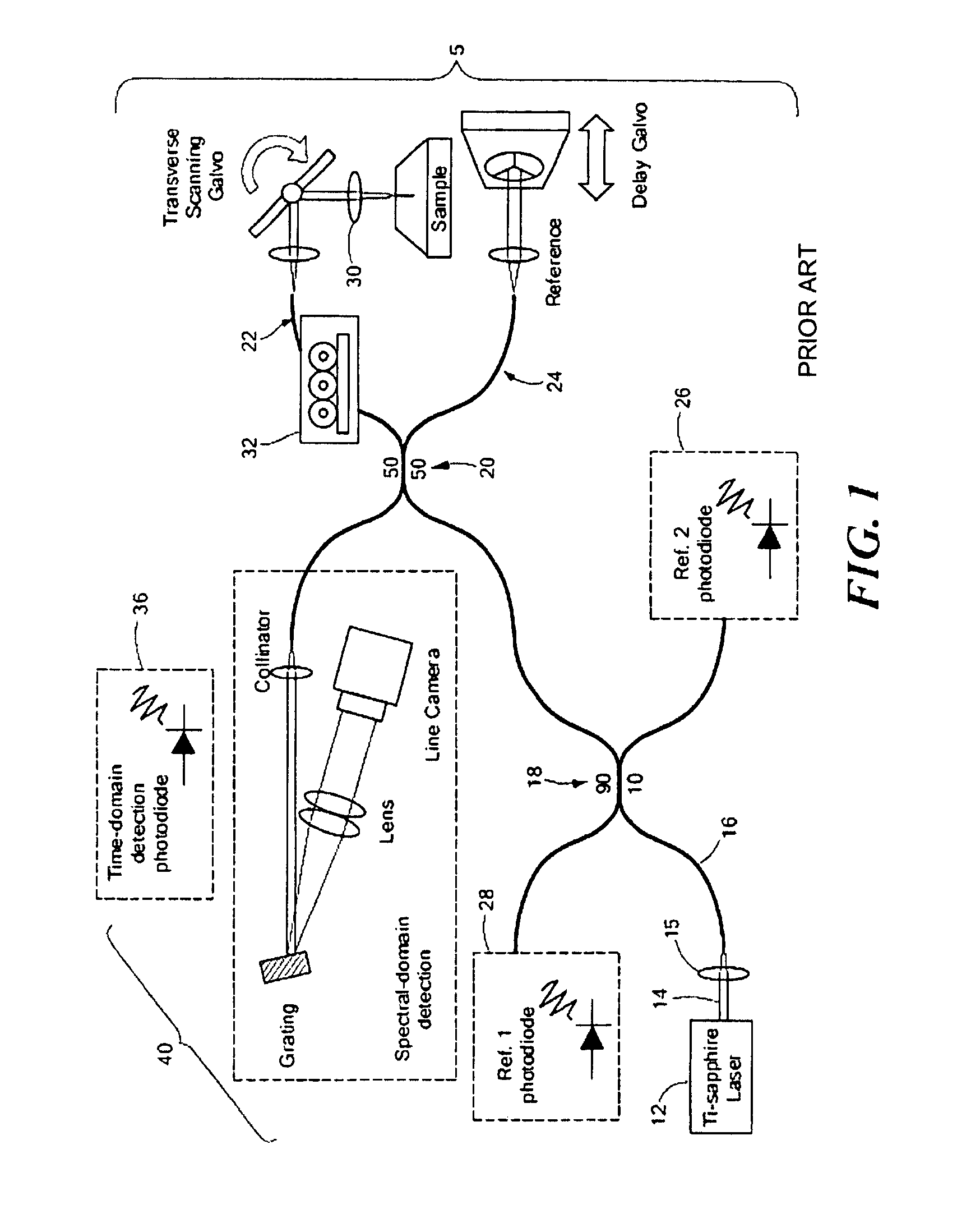
[0037]FIG. 1 shows an example of an OCT system, designated generally by numeral 5, including options to detect the cross-correlation signal in either the spectral domain or the time domain. This particular OCT system uses a coherent light source 12, such as a neodymium:vanadate (Nd:YVO4) pumped titanium:sapphire laser. In the exemplary embodiment depicted, a center wavelength of 800 nm and an average bandwidth of 100 nm yields an axial resolution of ˜2 μm in tissue. The beam 14 is launched, via coupling optics 15, into a fiber-optic cable 16 and connected to a pair of fiber-optic beam splitters 18, 20 (Gould Fiber Optics, Inc., Millersville, Md.). The interferometer employs a single-mode 50 / 50 fiber optic splitter 2...


PUM


Abstract

Methods and apparatus for three-dimensional imaging of a sample. A source is provided of a beam of substantially collimated light characterized by a temporally dependent spectrum. The beam is focused in a plane characterized by a fixed displacement along the propagation axis of the beam, and scattered light from the sample is superposed with a reference beam derived from the substantially collimated source onto a focal plane detector array to provide an interference signal. A forward scattering model is derived relating measured data to structure of an object to allow solution of an inverse scattering problem based upon the interference signal so that a three-dimensional structure of the sample may be inferred in near real time.

Description

[0001]The present application claims the priority of U.S. Provisional Patent Application Ser. No. 60 / 819,593, filed Jul. 10, 2006, which is incorporated herein by reference.[0002]The present invention has been developed, in part, with Government support under Contract Numbers 02390265 and BES 05-19920, awarded by the National Science Foundation, and Contract Number 1 R21 EB005321, awarded by the National Institutes of Health. The Government has certain rights in the invention.TECHNICAL FIELD[0003]The present invention pertains to a computed imaging method for three-dimensional interferometric determination of the susceptibility of an object on the basis of coherently detected backscattered radiation, and, more particularly, to a method for providing improved resolution outside of the limited volume (the confocal volume) that can be resolved in focus for typical optical, acoustic, and other microscopes.BACKGROUND OF THE INVENTION[0004]Optical coherence tomography (OCT), as employed f...

Claims


Application Information

Patent Timeline
Patent Type & Authority Patents(United States)
IPC IPC(8): G01B11/02
CPCG01N21/4795G02B27/58G02B21/0064G02B21/0056G01B9/02004G01B9/02091
Inventor RALSTON, TYLER S.MARKS, DANIEL L.CARNEY, PAUL SCOTTBOPPART, STEPHEN A.
Owner THE BOARD OF TRUSTEES OF THE UNIV OF ILLINOIS
Why Eureka
Try Eureka