LED lighting apparatus with transparent flexible circuit structure

a flexible circuit and lighting apparatus technology, applied in lighting and heating apparatus, lighting support devices, dielectric characteristics, etc., can solve the problems of limiting the size, dimensions, shape and viewing effect of an applied product, and achieve the effect of improving the prettification and diversion effect and enhancing the stereo design

Inactive Publication Date: 2009-10-20
POLYTRON TECH
View PDF13 Cites 66 Cited by
  • Summary
  • Abstract
  • Description
  • Claims
  • Application Information

AI Technical Summary

Benefits of technology

[0007]Another object of this invention is to provide a plane structure of light-emitting diode lighting apparatus. Conductive material and insulating pattern are formed on a flexible tape, which may stack one layer or multiple layers of LEDs to diversify the LED deployment and enhance the stereo design to improve effect of prettification and diversion.

Problems solved by technology

However, the application of LED is provided generally with LEDs associated with the layout of circuit fixed or attached onto a hard and opaque carrier, which limits the size, dimensions, shape and viewing effect for an applied product.

Method used


Image

  • LED lighting apparatus with transparent flexible circuit structure
  • LED lighting apparatus with transparent flexible circuit structure
  • LED lighting apparatus with transparent flexible circuit structure

Examples


first embodiment

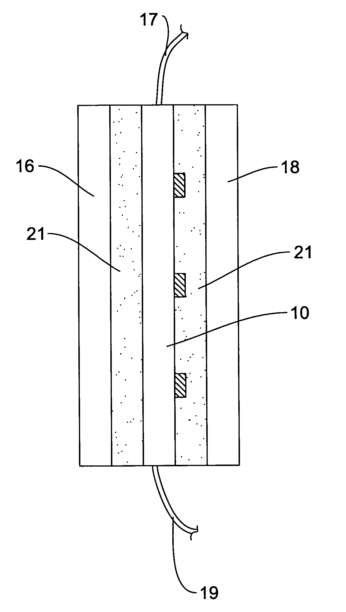
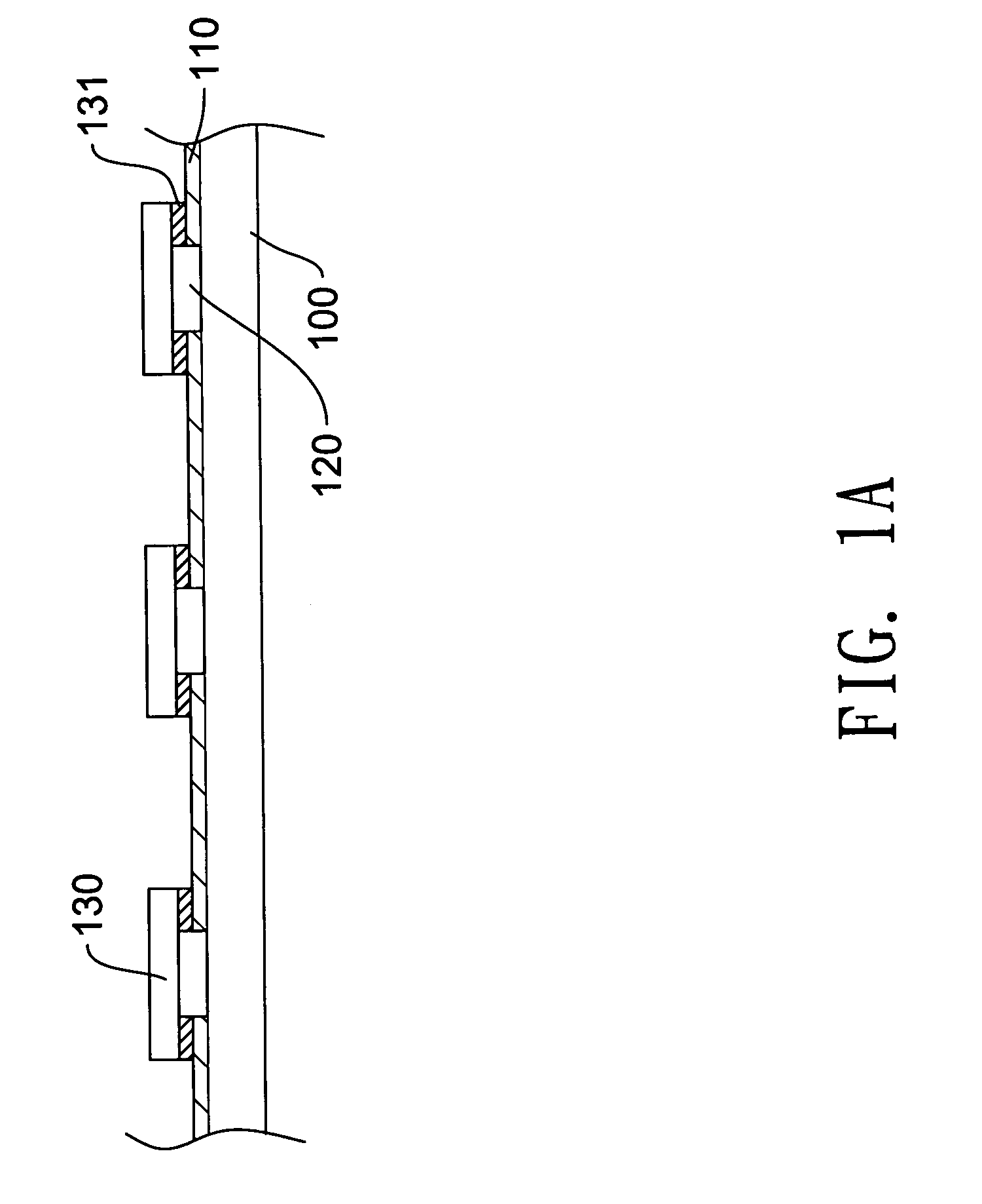
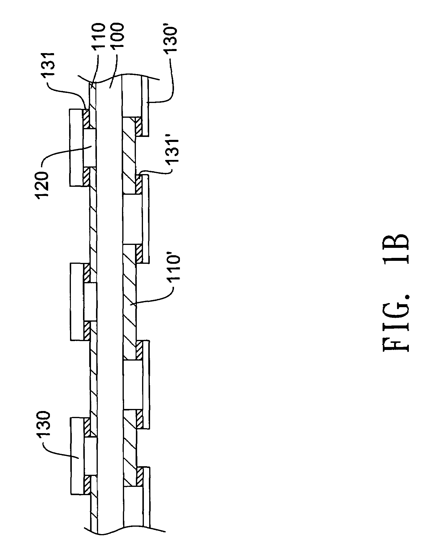
[0021]FIG. 1A is a cross-sectional diagram of a plane structure of an LED lighting apparatus in accordance with the present invention. An LED lighting apparatus includes a first transparent pattern and a second transparent pattern 120 on a transparent flexible tape 100. One or more first LEDs 130 are attached to the first transparent pattern with adhesive structures 131. In one embodiment, the transparent flexible tape 100 is made of insulating and flexible material, such as poly (ethylene terephthalate) (PET), poly carbonate (PC), oriented polypropylene (OPP), poly vinylchlorid (PVC), acrylic or other polymer material, but not limited to. Next, the first transparent pattern, such as a first transparent conductive line 110, but not limited to, is made of such as ITO (Indium Tin Oxide), IZO (Indium Zinc Oxide), or acrylic transparent conductive gel, which is formed on the transparent flexible tape 100 by silk screening or printing. It is appreciated that the first transparent conduct...

third embodiment

[0024]FIG. 2A is a cross-sectional diagram illustrating the plane structure of the LED lighting apparatus in accordance with the present invention. A first transparent pattern is disposed on a transparent flexible tape 400, and, in this embodiment, the first transparent pattern is a transparent conductive film 420, which is divided into a first zone 460 and a second zone 470 by a second transparent pattern 410. In the embodiment, the transparent conductive film 420, not limited to, is made of transparent conductive material such as ITO or IZO, which is formed on the transparent flexible tape 400 by sputtering, evaporate plating, printing or attaching. It is understood that the transparent conductive film 420 may be made with a conductive material implanted a dye or dyes for visual arts. Next, the second transparent pattern 410 will be formed on the transparent conductive film 420 as an insulating pattern by a suitable method, such as laser, chemically etching, printing or cutting, t...


PUM


Abstract

A light-emitting diode (LED) lighting apparatus includes a transparent flexible tape with a first transparent pattern and a second transparent pattern, the first transparent pattern being insulated from the second transparent pattern. A plurality of light-emitting diodes is electrically connected with the first transparent pattern. The LED lighting apparatus can also form the first transparent pattern and the second transparent pattern on two sides of the transparent flexible tape, or, furthermore, to form the first transparent pattern and the second transparent pattern stack to generate a multi-story LED lighting apparatus. Such a plane of emitting diode is applied to various display, furniture decoration and lighting.

Description

BACKGROUND OF THE INVENTION[0001]1. Field of the Invention[0002]The present invention relates to a plane structure of a lighting apparatus and more especially, relates to a plane structure of a light-emitting diode lighting apparatus.[0003]2. Description of the Prior Art[0004]With the development and progress of the technology, light-emitting diode (LED) plays an important role on various application due to its low thermal dissipation, low power consumption, long life, quick response, small volume, good vibration resistance, no gas discharge and plate package. Thus, LED may be applied on the products of lighting, prospect design, transportation instruction and electric display.[0005]For example, on the application of prospect beautification, a lighting system with LED may present effects on the varieties of color light not only to provide the function of ambient lighting but also to generate colorful enrichment with low power consumption. However, the application of LED is provided ...

Claims


Application Information

Patent Timeline
Patent Type & Authority Patents(United States)
IPC IPC(8): F21S13/14H01L33/16H01L33/62
CPCH05K1/0274H01L24/45F21S4/006H05K1/189H05K2201/0108H05K2201/0326H05K2201/10106H01L2224/45H01L2924/01047H01L2924/00014H01L2924/01006H01L2924/00H01L2224/48H01L2924/0002H01L2924/12041H01L24/48H01L2224/48137F21S4/24F21Y2109/00H01L2224/45099
Inventor YU, SAMCHENG, DALONG
Owner POLYTRON TECH
Why Eureka
Try Eureka