
Method of manufacturing non-volatile memory device

a non-volatile memory and semiconductor technology, applied in the direction of semiconductor memory devices, basic electric elements, electrical appliances, etc., can solve the problems of reducing the reliability and affecting the operation of the non-volatile memory device. , to achieve the effect of reducing the leakage current through the lower, middle and upper dielectric layers

Active Publication Date: 2009-10-20
SAMSUNG ELECTRONICS CO LTD
View PDF7 Cites 0 Cited by
  • Summary
  • Abstract
  • Description
  • Claims
  • Application Information

AI Technical Summary

Benefits of technology

[0011]Exemplary embodiments of the present invention provide a method of manufacturing a non-volatile memory device including a blocking layer having improved electrical characteristics.
[0021]According to the exemplary embodiments of the present invention, the lower, middle and upper dielectric layers may be sufficiently densified by the heat treatment processes. Thus, the leakage current through the lower, middle and upper dielectric layers may be reduced.

Problems solved by technology

However, the volatile semiconductor memory devices may lose data stored therein when power is shut off.
However, when a hafnium aluminum oxide layer is used as the blocking layer, though the leakage current characteristic may be improved, the reliability of the non-volatile memory device may be deteriorated due to shallow trap sites in the hafnium aluminum oxide layer.
In detail, electrons may be trapped in the shallow trap sites in the hafnium aluminum oxide layer from the control gate electrode and / or the float gate electrode, and thus the high temperature stress (HTS) characteristic and threshold voltage window characteristic in the non-volatile memory device may be deteriorated.
Thus, when the blocking layer including the lower aluminum oxide layer, the middle hafnium oxide layer and the upper aluminum oxide layer is employed in a non-volatile memory device, the break down voltage characteristics of the non-volatile memory device may be deteriorated.

Method used


Image

  • Method of manufacturing non-volatile memory device
  • Method of manufacturing non-volatile memory device
  • Method of manufacturing non-volatile memory device

Examples


Embodiment Construction

[0025]The present invention may, however, be embodied in many different forms and should not be construed as limited to the exemplary embodiments set forth herein. Like reference numerals refer to like elements throughout.

[0026]It will be understood that when an element is referred to as being “on” another element, it can be directly on the other element or intervening elements may be present. In contrast when an element is referred to as being “directly on” another element, there are no intervening elements present. As used herein, the term “and / or” includes any and all combinations of one or more of the associated listed items.

[0027]It will be understood that, although the terms first, second, etc. may be used herein to describe various elements, these elements should not be limited by these terms. These terms are only used to distinguish one element from another. For example, a first thin film could be termed a second thin film, and, similarly, a second thin film could be termed ...


PUM

PropertyMeasurementUnit
temperatureaaaaaaaaaa
partial pressureaaaaaaaaaa

Abstract

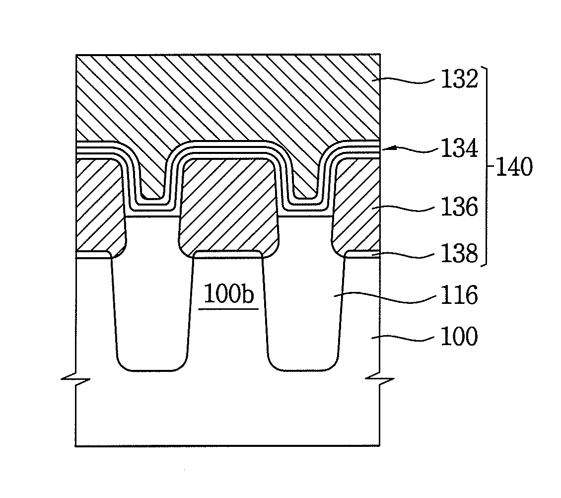
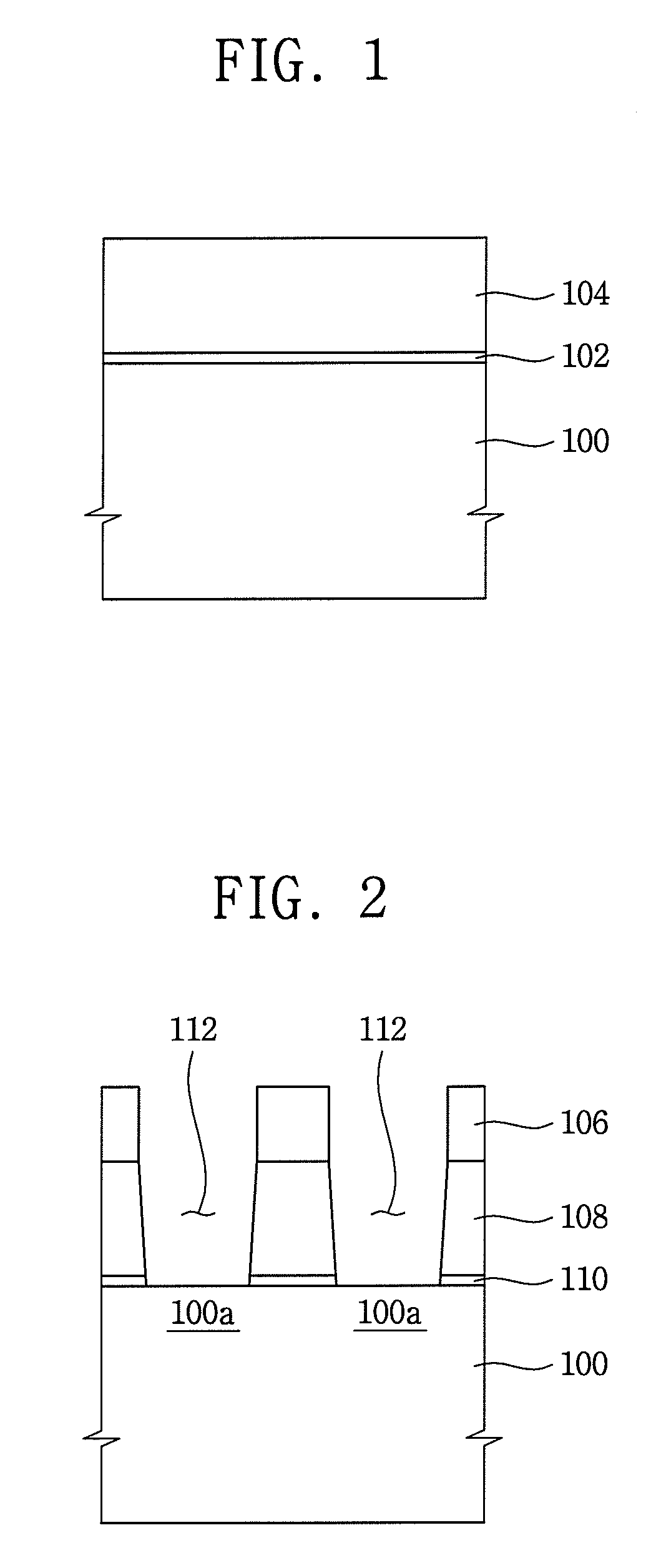
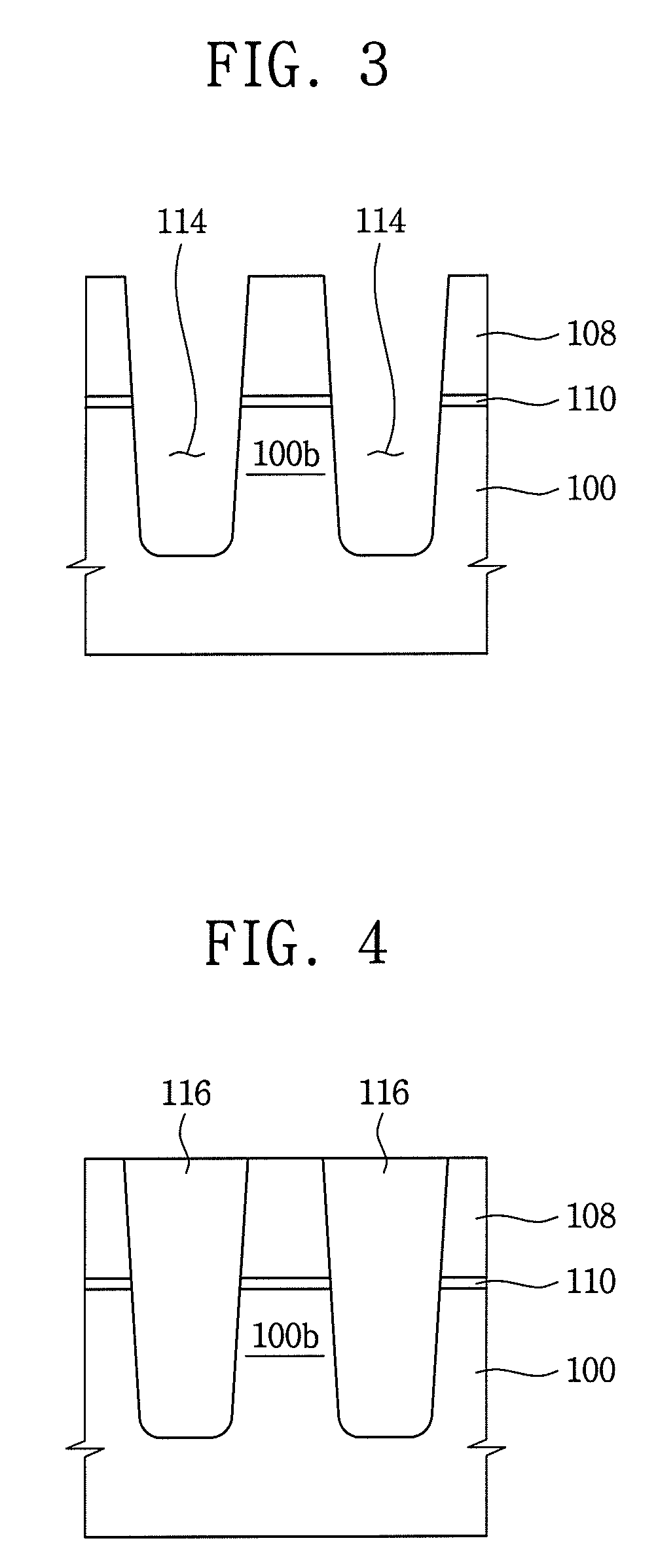
A method of manufacturing a non-volatile memory device includes forming a tunnel insulating layer on a substrate, forming a conductive pattern on the tunnel insulating layer, forming a lower dielectric layer on the conductive pattern, performing a first heat treatment process to density the lower dielectric layer, and forming a middle dielectric layer having an energy band gap smaller than that of the lower dielectric layer on the first heat-treated lower dielectric layer. The method further includes forming an upper dielectric layer including a material substantially identical to that of the lower dielectric layer on the middle dielectric layer, performing a second heat treatment process to densify the middle dielectric layer and the upper dielectric layer and forming a conductive layer on the second heat-treated upper dielectric layer.

Description

CROSS-REFERENCE TO RELATED APPLICATION[0001]This application claims priority under 35 USC § 119 to Korean Patent Application No. 2006-99212 filed on Oct. 12, 2006, the disclosure of which is hereby incorporated by reference herein in its entirety.BACKGROUND OF THE INVENTION[0002]1. Technical Field[0003]The present disclosure relates to a method of manufacturing a non-volatile memory device. More particularly, the present disclosure relates to a method of manufacturing a non-volatile memory device including a floating gate electrode.[0004]2. Description of the Related Art[0005]Semiconductor memory devices, in general, are typically classified as either volatile or non-volatile semiconductor memory devices. Volatile semiconductor memory devices such as dynamic random access memory (DRAM) devices and / or static random access memory (SRAM) devices have a relatively high response speed. However, the volatile semiconductor memory devices may lose data stored therein when power is shut off....

Claims


Application Information

Patent Timeline
Patent Type & Authority Patents(United States)
IPC IPC(8): H01L21/3205
CPCH01L27/11521H01L27/115H10B69/00H10B41/30H01L29/40114
Inventor PARK, KI-YEONKIM, SUN-JUNGRYU, MIN-KYUNGLEE, SEUNG-HWANCHOI, HAN-MEI
Owner SAMSUNG ELECTRONICS CO LTD
Learn More