Motor, blower, compressor, and air conditioner

a technology for compressors and motors, applied in the direction of magnetic circuit rotating parts, mechanical energy handling, magnetic circuit shape/form/construction, etc., can solve problems such as difficulties in thinning the motor

Inactive Publication Date: 2009-10-27
DAIKIN IND LTD
View PDF26 Cites 28 Cited by
  • Summary
  • Abstract
  • Description
  • Claims
  • Application Information

AI Technical Summary

Benefits of technology

[0014]To employ a structure in which a magnetic-field creating magnet and an armature winding face each other in a radial direction would increase the size and the length of a magnetic path formed during rotational movement of a motor and also increase the number of air gaps in the magnetic path, to increase magnetic reluctance. As a result, efficiency and torque are reduced. As such, the motor having the foregoing structure could not be suitably applied to a blower of an air conditioner, for example, whose efficiency is particularly weighed heavily.
[0015]On the other hand, during rotational movement of the rotor, a magnetic flux of the magnetic-field creating magnet of the rotor travels while also extending orthogonally to the flat portion of the yoke plate of the stator. Accordingly, an induced eddy current occurs in a direction extending from the rotation axis toward a periphery, or in a direction opposite thereto, in the yoke plate by Fleming's right-hand rule. Such occurrence of an eddy current causes reduction in the efficiency of the motor.
[0016]In view of the foregoing, it is the first object of the present invention to provide a technique for improving the efficiency and the torque of a motor while achieving thinning of the motor.

Problems solved by technology

However, when a magnet for creating a field magnet and an armature winding face each other in an axial direction as described above, respective widths of the magnetic-field creating magnet and the armature winding, which widths extend in the axial direction, are added to each other, to have difficulties in thinning the motor.

Method used


Image

  • Motor, blower, compressor, and air conditioner
  • Motor, blower, compressor, and air conditioner
  • Motor, blower, compressor, and air conditioner

Examples


first embodiment

[0019]A second aspect of the motor according to the present invention is the motor in which the one ends of the adjacent first yoke plates (41) are connected to each other.

[0020]A third aspect the motor according to the present invention is the first embodiment of the motor in which the other ends of the adjacent first yoke plates (41) are connected to each other such that a junction between the other ends of the adjacent first yoke plates (41) does not overlie a boundary between the north pole and the south pole.

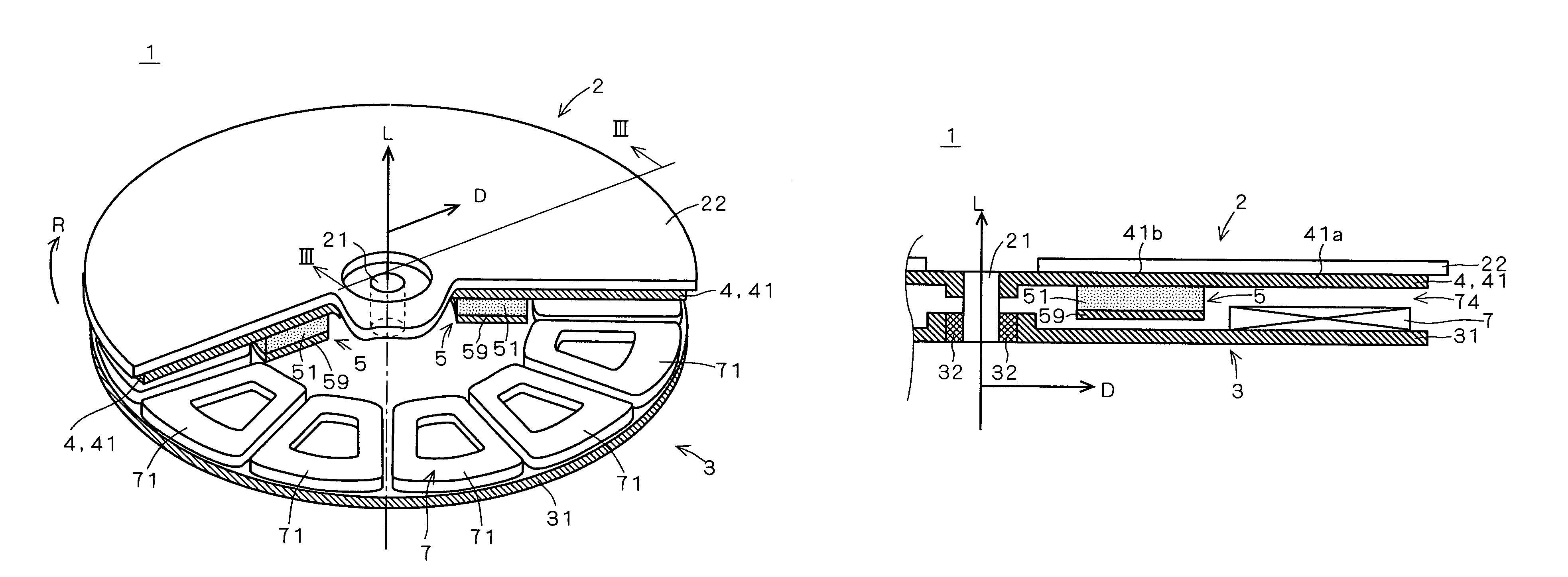
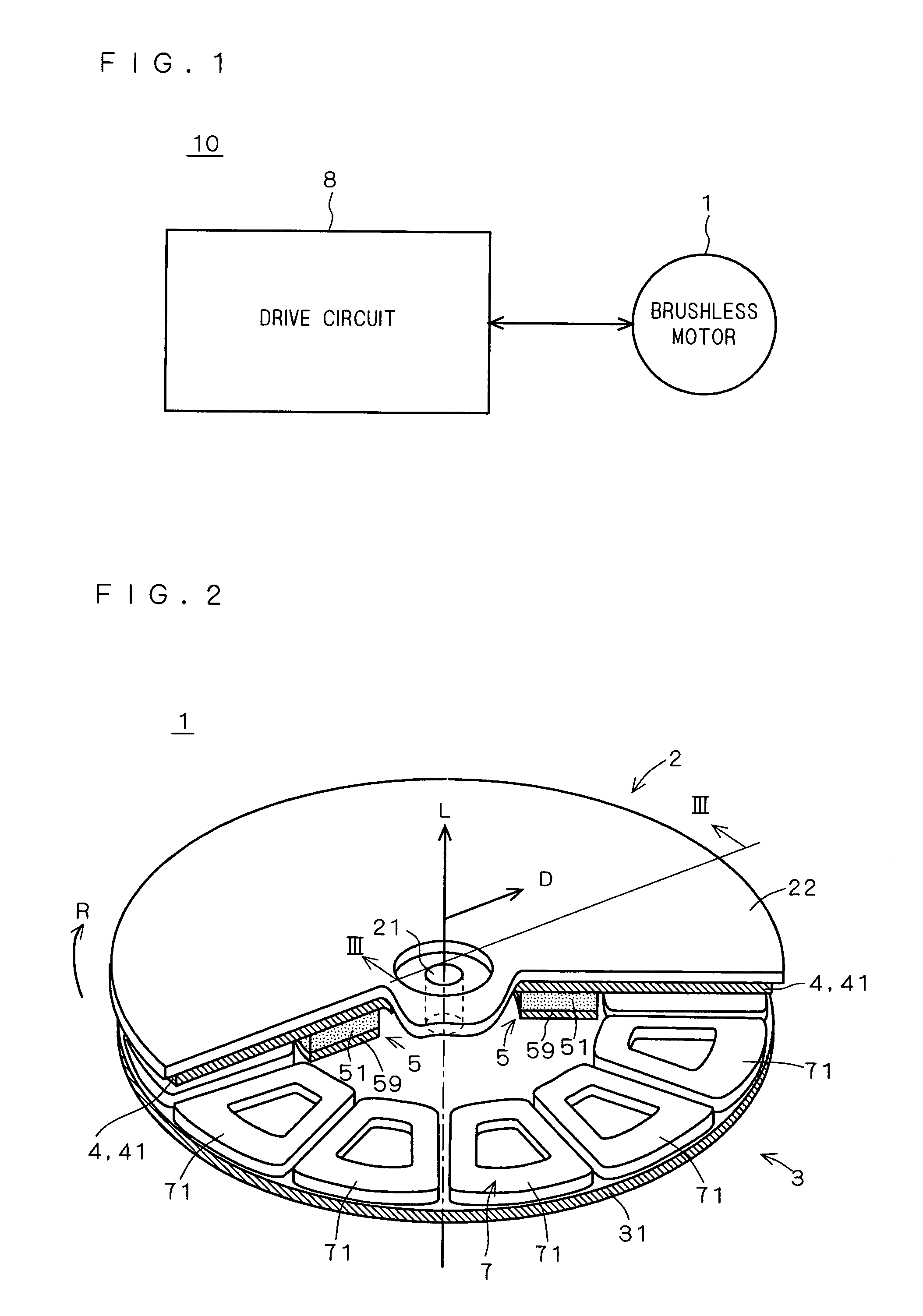
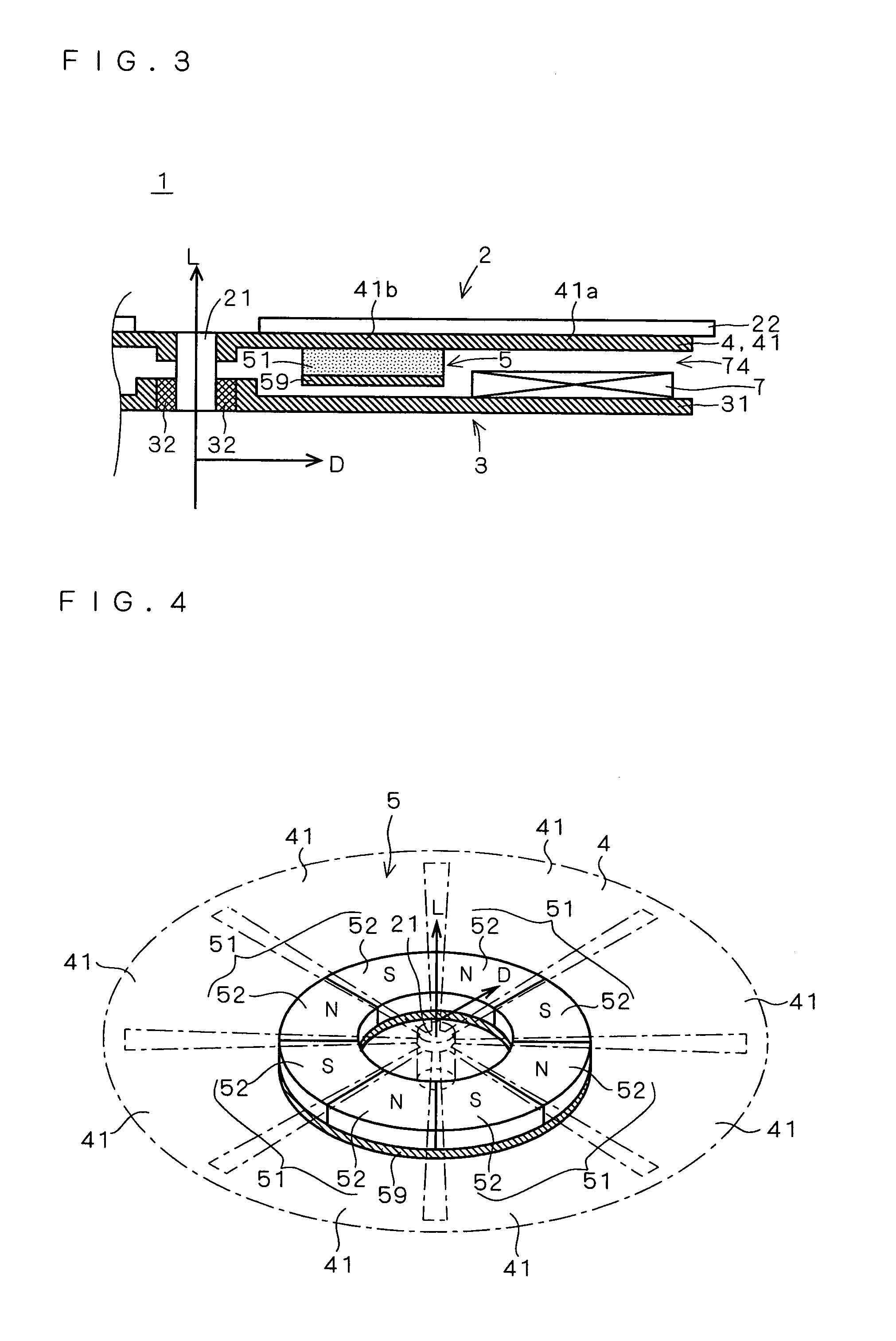
[0021]A fourth aspect of the motor according to the present invention is the first embodiment of the motor in which each of the plurality of first yoke plates (41) includes a linear outline (411) parallel to the second direction (D).

[0022]A fifth aspect of the motor according to the present invention is the first embodiment of the motor in which an interval (461) between the adjacent first yoke plates (41) increases as a distance from the rotation axis (21) increases in the...

fifth embodiment

[0023]A sixth aspect of the motor according to the present invention is the motor in which the interval (461) between the adjacent first yoke plates (41) non-linearly increases in proportion to the distance from the rotation axis (21).

[0024]A seventh aspect of the motor according to the present invention is the first embodiment of the motor in which the magnetic-field creating magnet (5) is disc-shaped.

[0025]An eighth aspect of the motor according to the present invention is the first embodiment of the motor in which the magnetic-field creating magnet (5) includes: at least one permanent magnet (51) in which a north pole and a south pole are laid side by side in the first direction (L); and a second yoke plate (59) which joins the north pole and the south pole of the permanent magnet on a side opposite to a side on which the plurality of first yoke plates (41) are placed.

[0026]A ninth aspect of the motor according to the present invention is the first embodiment of the motor in whic...

eighth embodiment

[0027]A tenth aspect of the motor according to the present invention is the motor in which the permanent magnet (51, 53) is a bonded-magnet.


PUM


Abstract

It is an object of the present invention to provide techniques for improving efficiency and torque of a motor while achieving thinning of the motor. In a brushless DC motor, a rotor includes a magnetic-field creating magnet and a stator includes an armature winding. The magnetic-field creating magnet and the armature winding are placed to locally face in a radial direction orthogonal to an axial direction. This reduces a thickness of the brushless DC motor which extends in the axial direction. Also, a short-circuit yoke plate for joining and magnetically short-circuiting the north pole and the south pole of a permanent magnet is placed on a negative side in the axial direction with respect to the magnetic-field creating magnet. By provision of the short-circuit yoke plate, a magnetic path on a negative side in the axial direction with respect to the magnetic-field creating magnet can be shortened. Accordingly, magnetic reluctance occurring during rotational movement of the brushless DC motor can be reduced, to thereby improve efficiency and torque of the brushless DC motor.

Description

CROSS-REFERENCE TO RELATED APPLICATIONS[0001]This U.S. National stage application claims priority under 35 U.S.C. §119(a) to Japanese Patent Application Nos. 2004-104539 and 2004-104540, filed in Japan on Mar. 31, 2004, the entire contents of which are hereby incorporated herein by reference.TECHNICAL FIELD[0002]The present invention relates to techniques for a motor including an armature and a field element which are rotatable relative to each other on a rotation axis.BACKGROUND ART[0003]A known example of a motor including an armature and a field element which are rotatable relative to each other on a rotation axis is an axial gap brushless DC motor (which will hereinafter be simply referred to as a “brushless motor”). In general, in an axial gap brushless motor, a rotor includes a magnetic-field creating magnet and a stator includes an armature winding and a yoke plate. Then, a structure in which the magnetic-field creating magnet and the armature winding face each other in an ax...

Claims


Application Information

Patent Timeline
Patent Type & Authority Patents(United States)
IPC IPC(8): H02K21/12H02K1/12H02K1/22H02K1/27H02K7/14H02K21/24H02K29/08
CPCH02K21/24H02K7/14
Inventor YAMAGIWA, AKIO
Owner DAIKIN IND LTD
Why Eureka
Try Eureka