Equipment and method for band allocation

a technology of equipment and bandwidth, applied in the field of equipment and a bandwidth allocation method, can solve the problems of wasting bandwidth, increasing the cost of a system, and reducing the efficiency of the system, so as to achieve speed up the bandwidth allocation control, no decrease in bandwidth efficiency, and the effect of rapid processing

Active Publication Date: 2009-10-27
NEC CORP
View PDF6 Cites 1 Cited by
  • Summary
  • Abstract
  • Description
  • Claims
  • Application Information

AI Technical Summary

Benefits of technology

[0026]The present invention relates to a bandwidth allocation equipment that allocates bandwidth for data sent from each Optical Network Unit (ONU) to the Optical Line Terminal (OLT) through the optical splitter in consideration to the priorities. The bandwidth allocation equipment comprises a transmit / receive unit for communicating with each optical network unit, and receives an output request as a data transmission request from each optical network unit. The bandwidth allocation equipment sends back transmittable data types in a service cycle as a unit period for the data transmission and bandwidth to be allocated to the data as a signal sending permission to each optical network unit. The output request decides time-divisioned bandwidth allocation in the service cycle as the unit period wherein each optical network unit transmits data to the optical line terminal. If data transmission beyond the Maximum of Service Cycle is requested, bandwidth allocated to each of the optical network units must be controlled. In the present invention, an ONU (Optical Network Unit) bandwidth allocation unit provided for each of the optical network units allocates bandwidth depending on the priorities. The ONU bandwidth allocation units are located in a ring, and even processing is possible by shifting ONU bandwidth allocation units that allocates bandwidth for each service cycle. Even if there are many optical network units, rapid processing is possible since each ONU bandwidth allocation unit can only control bandwidth allocation for the optical network unit assigned to it. As a result, the bandwidth allocation control is sped up, causing no decrease in bandwidth efficiency.
[0027]As described above, according to the present invention, the ONU bandwidth allocation unit is provided to send data from each optical network unit to the optical line terminal through the optical splitter. With the bandwidth allocation unit, bandwidth allocation can be processed depending on the status of respective optical network units. If the optical network units increase, the ONU bandwidth allocation units can increase accordingly, therefore there is no redundancy in a configuration of a communication system. If there is a plurality of ONU bandwidth allocation units and some of them suffer problems, other optical network units can substitute for the processing, so that reliability of the communication system improves.

Problems solved by technology

Accordingly, large amount of data such as image data or video data is often communicated, raising an important issue of improving a communication line to a broadband to allow wideband access to the Internet.
However, since it does not define an upstream bandwidth allocation method or algorithm, these can be defined in equipment design as necessary.
However, the conventional algorithm has a problem of system scalability.
By this reason, in a large-scale PON, the bandwidth allocation control unit 121 needs an expensive and high-speed integrated circuit or a CPU, which raises the cost of a system.
Additionally, if sufficient time is allowed for the bandwidth allocation to solve this problem, starting time of the service cycle SC delays and bandwidth is wasted.
As a result, there is a problem that the bandwidth allocation is constrained particularly for the AF data and BE data classes and system performance degrades.

Method used


Image

  • Equipment and method for band allocation
  • Equipment and method for band allocation
  • Equipment and method for band allocation

Examples


embodiment 1

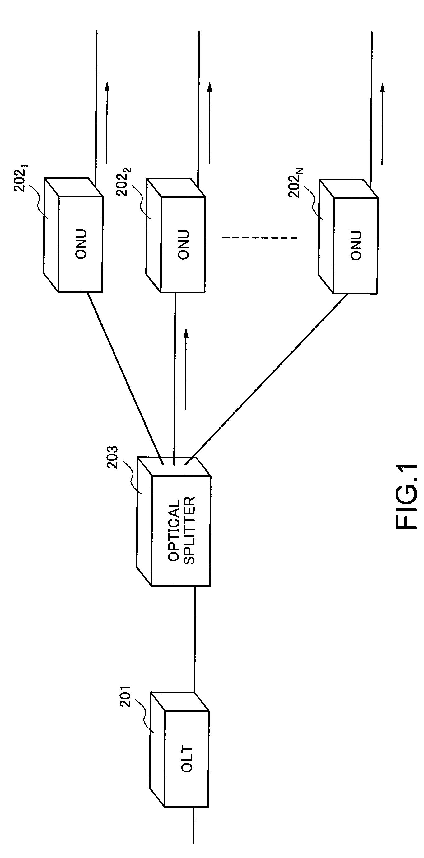
[0045]FIG. 1 illustrates an overview of a PON in one embodiment of the present invention. An OLT 201 in the present embodiment connects to first to Nth ONUs 2021-202N located correspondingly to end users' homes respectively via an optical splitter 203. The OLT 201 connects to a communication network (not shown) such as the Internet. The first to Nth ONUs 2021-202N connect to communication terminals such as personal computers (not shown). The first to Nth ONUs 2021-202N and the optical splitter 203 have substantially identical configurations to those of the first to Nth ONUs 1021-102N and the optical splitter 103 shown in FIG. 11. These configurations are not further described herein. In the present embodiment, a bandwidth allocation control unit of the OLT 201 differs from the bandwidth allocation control unit 121 shown in FIG. 15. Other components of the OLT 201 are substantially identical to those of the OLT 101 shown in FIG. 11.

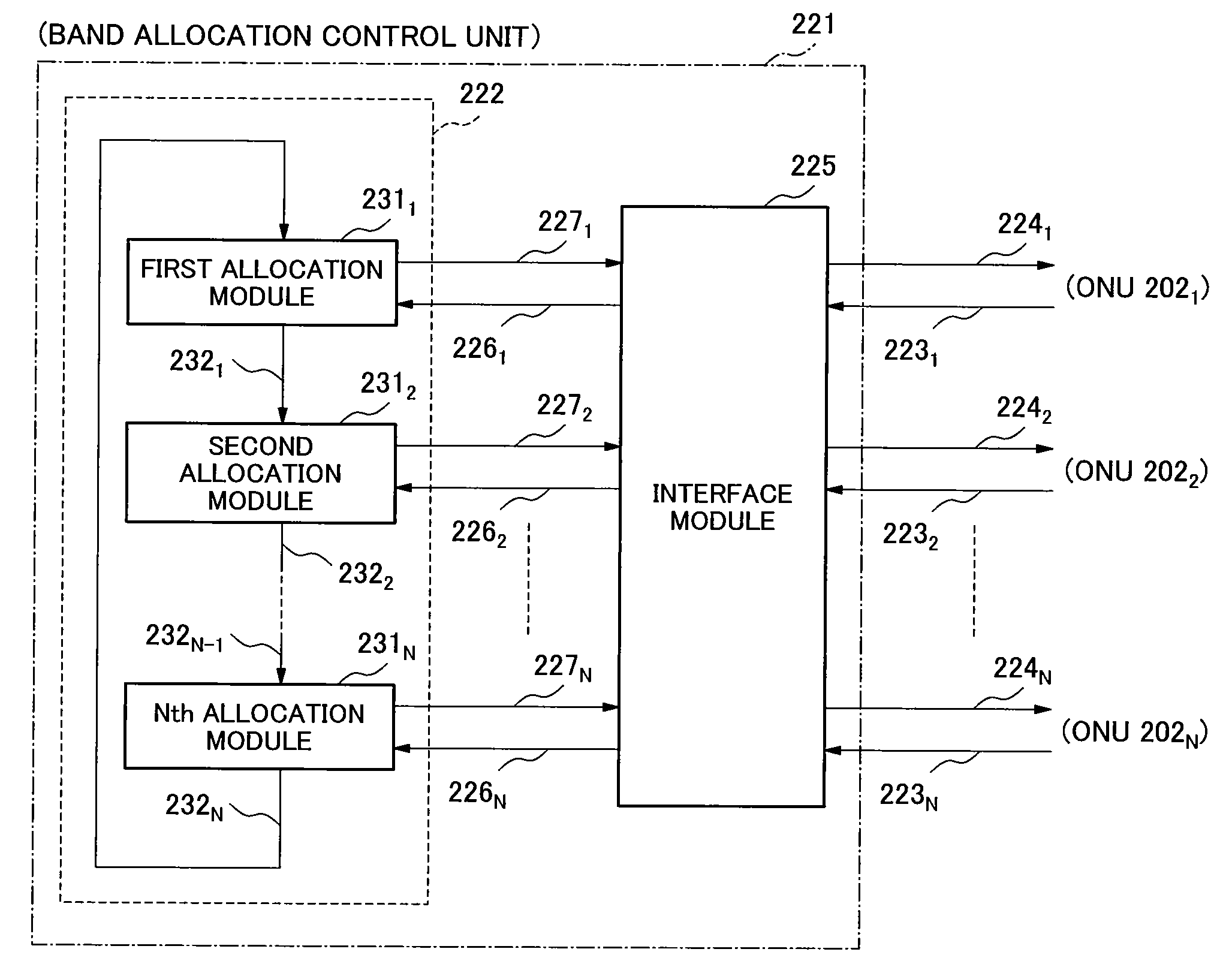
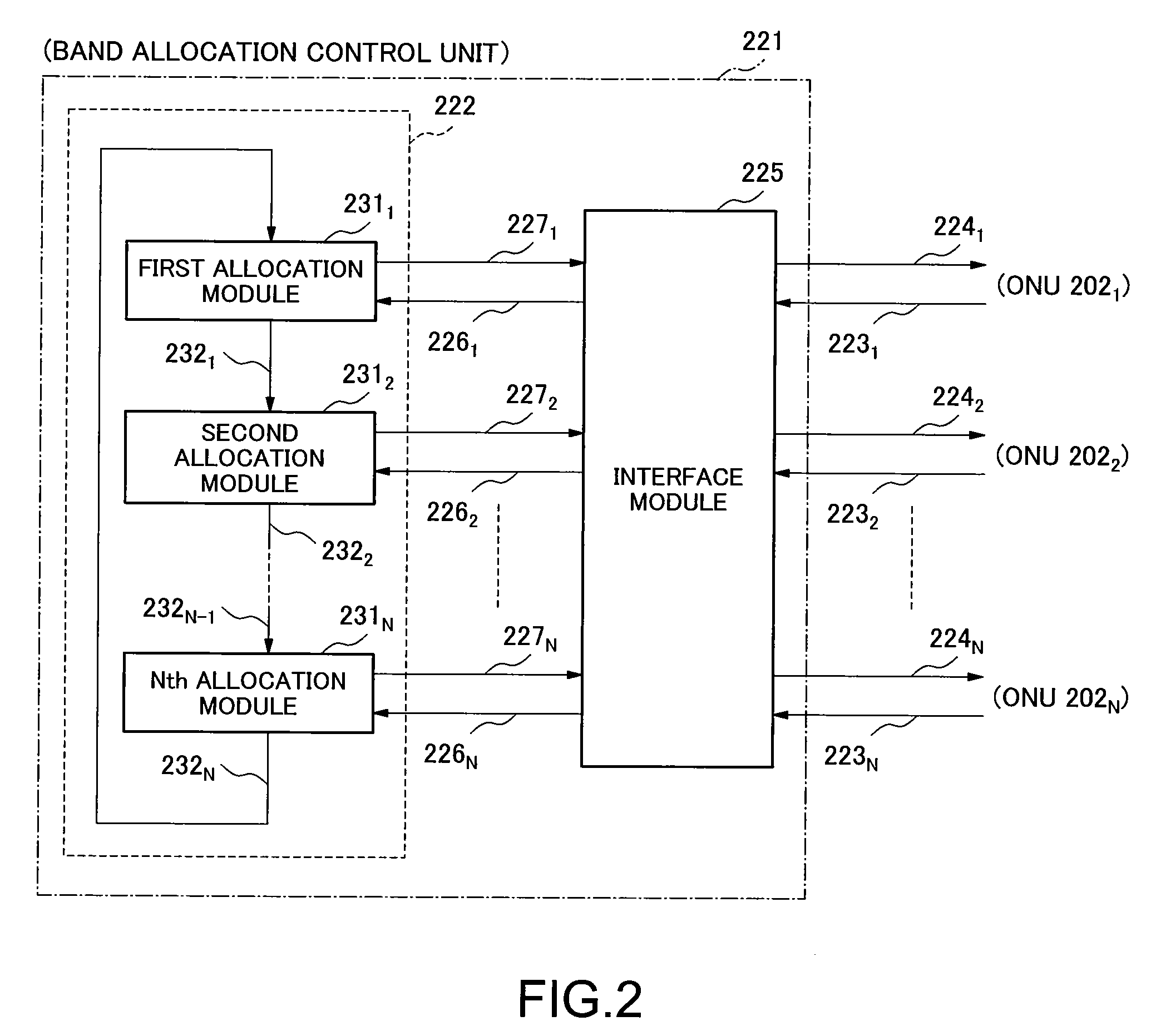
[0046]FIG. 2 illustrates a configuration of a bandwi...


PUM


Abstract

A bandwidth allocation equipment in an optical line terminal, which allocates bandwidth for data to be transmitted from optical network units through an optical splitter, includes a transmit / receive unit and bandwidth allocation units. The transmit / receive unit receives an output request for requesting bandwidth allocation, and sends back a signal sending permission to the respective optical network units for specifying bandwidth to be allowed for transmitting the data in each service cycle. The bandwidth allocation units are connected to one another in a ring. Each bandwidth allocation unit is provided with corresponding to the optical network unit, and outputs the signal sending permission from the bandwidth allocation unit that has performed the last bandwidth allocation processing in the ring connection. The transmit / receive unit specifies the bandwidth allocation unit that performs the first bandwidth allocation processing by shifting one by one for each of the service cycles.

Description

BACKGROUND OF THE INVENTION[0001]1. Field of the Invention[0002]The present invention relates to an equipment and a method for bandwidth allocation at an optical line terminal in the Passive Optical Network.[0003]2. Description of the Related Art[0004]The Internet is rapidly spreading and developing. Accordingly, large amount of data such as image data or video data is often communicated, raising an important issue of improving a communication line to a broadband to allow wideband access to the Internet. As a broadband access line, various types of technology have been put into practical use such as ADSL (Asymmetric Digital Subscriber Line) using existing telephone lines, or a cable modem using a coaxial line of CATV (Cable TeleVision) as a network line. However, for realization of high-speed and high-quality communication environment, it is desired that a communication line is further improved to a wideband. In such status, a PON (Passive Optical Network) as a network using optical...

Claims


Application Information

Patent Timeline
Patent Type & Authority Patents(United States)
IPC IPC(8): H04J3/16H04L12/44
CPCH04B10/27H04B10/272H04L12/56H04L47/11H04L47/12H04L47/2441H04L47/29H04Q11/0067H04L47/22H04Q2011/0088H04Q2011/0064
Inventor OZAKI, HIROKAZU
Owner NEC CORP
Why Eureka
Try Eureka