Process for the regeneration of a catalyst plant and apparatus for performing the process

a catalyst plant and process technology, applied in the field of process for the regeneration of catalyst plants and equipment for performing the process, can solve the problems of high cost, high consumption, high cost, etc., and achieve the effect of cost saving and substantial reduction of the consumption of regenerating gas

Inactive Publication Date: 2009-11-03
ANSALDO ENERGIA IP UK LTD
View PDF12 Cites 73 Cited by
  • Summary
  • Abstract
  • Description
  • Claims
  • Application Information

AI Technical Summary

Benefits of technology

[0005]The invention has as its object to provide a process of the category concerned, in which the consumption of regenerating gas is substantially reduced, without having to take account of the danger of a poisoning of the SCONOx catalyst by SO2. In one embodiment, the process extracts a regenerating gas from upstream of a SCOSOx catalyst or from between a SCOSOx catalyst and a SCONOx catalyst, introduces the extracted regenerating gas between the SCOSOx catalyst and the SCONOx catalyst or upstream of the SCOSOx catalyst, and introduces a fresh regenerating gas downstream of the SCONOx catalyst.
[0008]The invention provides a process of the category concerned, in which the regenerating gas is partially conducted in a closed circuit and hence is very well utilized, but transmission of the SO2 arising from the SCOSOx catalyst into the SCONOx catalyst is reliably prevented. The consumption of regenerating gas is substantially reduced, with a resulting cost savings in each case, but particularly when it consists of steam to a large extent.

Problems solved by technology

If the regenerating gas is passed only once through the catalyst, a very high consumption results, and correspondingly high costs arise.
In the described case, the production of the steam is costly in energy and correspondingly expensive, especially as demineralized water is required for its production.

Method used


Image

  • Process for the regeneration of a catalyst plant and apparatus for performing the process
  • Process for the regeneration of a catalyst plant and apparatus for performing the process
  • Process for the regeneration of a catalyst plant and apparatus for performing the process

Examples


Embodiment Construction

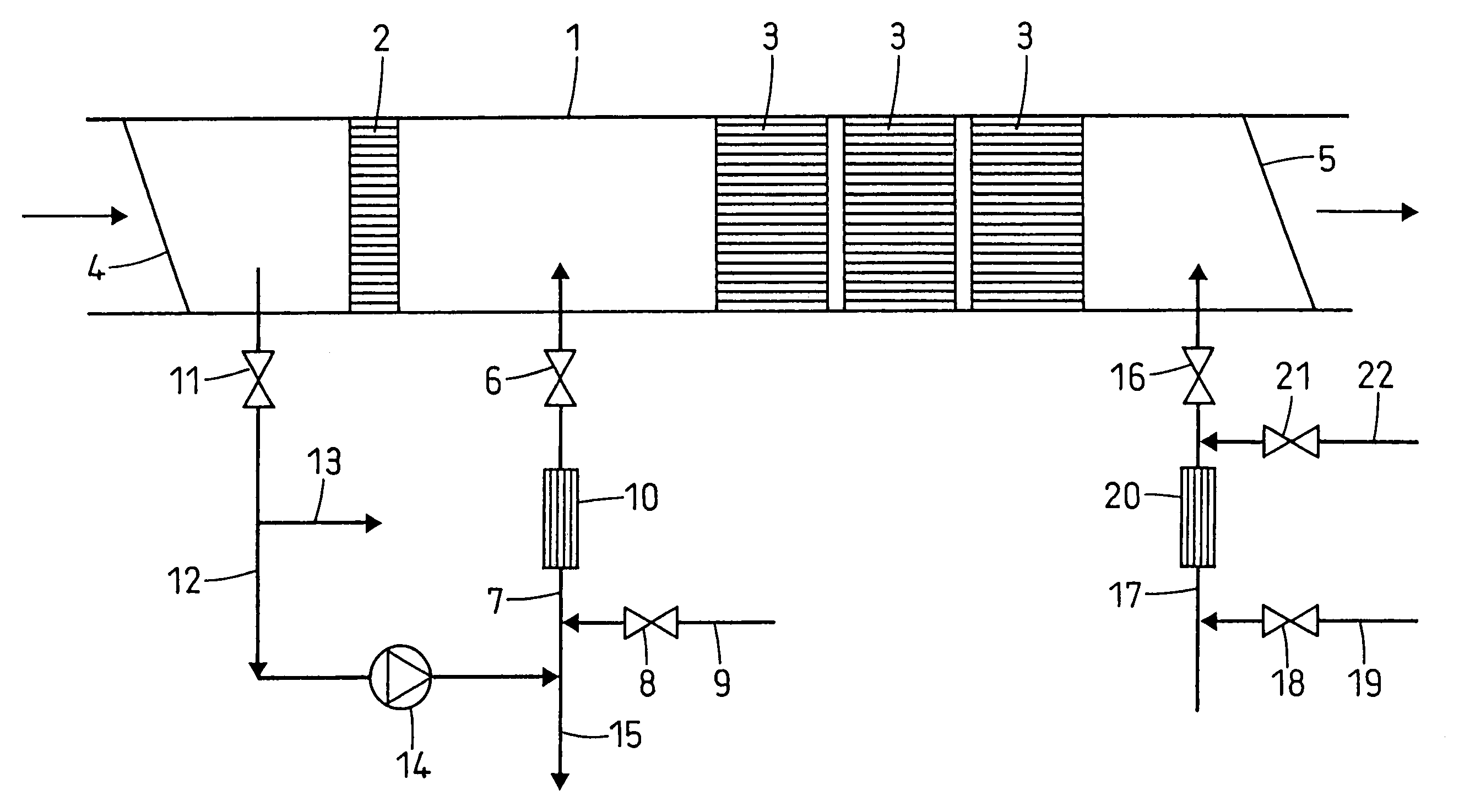
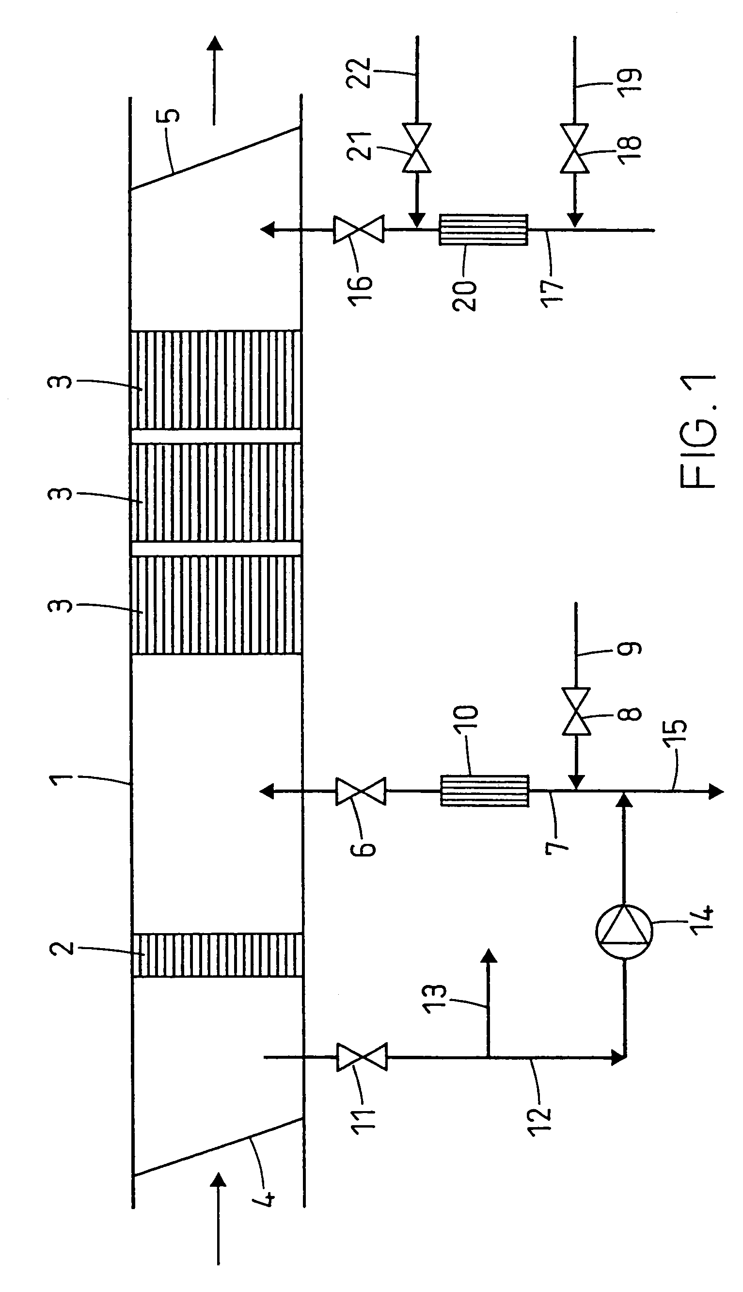
[0012]An apparatus according to the invention comprises (FIG. 1) a catalyst plant with a catalyst chamber 1, through which a portion of the flue gas of a gas turbine operated with natural gas, oil, synthesis gas or the like is conducted to a chimney, and in the latter, arranged in succession in the flow direction, a SCOSOx catalyst 2 for the removal of SO2 and a SCONOx catalyst 3 for the removal of NOx from the flue gas. By means of a first damper 4 arranged upstream and a second damper 5 arranged downstream, the SCOSOx catalyst 2 and the SCONOx catalyst 3 can be shut off from the flue gas stream.

[0013]A supply pipe 7 opens via an inlet valve 6 into the catalyst chamber 1 between the SCOSOx catalyst 2 and the SCONOx catalyst 3, and a supply pipe 9 opens into it via a feed valve 8. A steam reforming catalyst 10 is situated in the supply pipe 7 between the outlet of the supply pipe 9 and the feed valve 8. A drain pipe 12 leads via an outlet valve 11 from the catalyst chamber 1 between...


PUM

PropertyMeasurementUnit
energyaaaaaaaaaa
volume flowaaaaaaaaaa
volumeaaaaaaaaaa

Abstract

A gas stream containing e.g. molecular hydrogen is used for the regeneration of a catalyst for NOx and SO2 removal from the flue gas of a gas turbine. In order to reduce the consumption of regeneration gas, the gas inlet is located between the SCOSOx catalyst (2) and the SCONOx catalyst (3). The regeneration gas leaves the catalyst chamber upstream of the SCOSOx catalyst and is recycled. For the regeneration of the SCONOx catalyst and to keep SO2 containing gas from entering the SCONOx catalyst, a second regeneration gas inlet is located downstream of the SCONOx catalyst. The regeneration gas entering the catalyst chamber through this port passes the SCONOx (3) and the SCOSOx catalyst (2). The direction of the flow in the SCONOx catalyst can also be reversed. In another example, regeneration gas outlets are located both upstream of the SCOSOx and downstream of the SCONOx catalyst. But, only the regeneration gas from the SCONOx catalyst is recycled.

Description

[0001]This application is related to and claims priority under 35 U.S.C. § 119 to German Patent Application No. 100 49 040.9, filed Oct. 4, 2000, the entire contents of which are incorporated by reference herein. In addition, this application is a divisional of U.S. patent application Ser. No. 09 / 969,769 filed on Oct. 4, 2001, now U.S. Pat. No. 6,946,419, the entire contents of which are incorporated by reference herein.FIELD OF THE INVENTION[0002]The invention relates to a process for the regeneration of a catalyst plant for the removal of SO2 and NOx from the flue gas of a gas turbine, and also to an apparatus for carrying out the process.BACKGROUND OF THE INVENTION[0003]It has been known for a long time to reduce the SO2 content and the NOx content of the flue gases from gas turbines to environmentally acceptable values by means of catalyst plants which comprise respectively a so-called SCOSOx catalyst for the removal of SO2 and, downstream of this, a SCONOx catalyst for the remo...

Claims


Application Information

Patent Timeline
Patent Type & Authority Patents(United States)
IPC IPC(8): B01D53/96B01D53/50B01D53/56B01D53/60B01D53/86
CPCB01D53/8653B01D53/8609
Inventor KAEFER, GISBERT
Owner ANSALDO ENERGIA IP UK LTD
Why Eureka
Try Eureka