Laser frequency stabilizing apparatus, method and computer program product for stabilizing laser frequency

a laser frequency and stabilizing technology, applied in the direction of laser details, electrical devices, wave amplification devices, etc., can solve the problems of inability to realize without difficulty, system is to be expensive, and the stabilization (or locking) of the oscillation frequency cannot follow the elapsed-time variation in tim

Active Publication Date: 2009-11-03
MITUTOYO CORP
View PDF6 Cites 19 Cited by
  • Summary
  • Abstract
  • Description
  • Claims
  • Application Information

AI Technical Summary

Benefits of technology

[0010]In view of the above problem, it is an object of the present invention to provide a laser frequency stabilizing apparatus, a method and a computer program product for stabilizing a laser frequency by which accuracy for measurement of an interval between saturated absorption lines is not required, and stabilizing of an oscillation frequency can follow elapsed-time variation even though an actuator having large elapsed-time variation is utilized.
[0011]In order to achieve the above object, an aspect of the present invention is directed to a laser frequency stabilizing apparatus for stabilizing an oscillation frequency of laser light. The laser frequency stabilizing apparatus stabilizes an oscillation frequency of laser light by causing pump light to resonate using a resonator including a pair of mirrors disposed at opposed positions to generate the laser light, and varying a resonator length on the basis of a saturated absorption line included in an optical output signal. In this case, the optical output signal is obtained by irradiating an absorption cell with the laser light. The laser frequency stabilizing apparatus of the present invention includes: a light detecting section for detecting the optical output signal; a differential signal detecting section for detecting a differential signal of the optical light signal; an actuator for varying the resonator length; a drive section for driving the actuator; and a control section for controlling the drive section on the basis of the differential signal. In this case, the control section determines saturated absorption lines on the basis of an output of the differential signal, selects a specific saturated absorption line on the basis of the number of determined saturated absorption lines and a combination of the determined saturated absorption lines, and stabilizes the oscillation frequency of the laser light at the specific saturated absorption line.
[0012]Since the laser frequency stabilizing apparatus has the configuration described above, the laser frequency stabilizing apparatus may have accuracy for measurement so as to be capable of identifying the number of saturated absorption lines. Thus, the laser frequency stabilizing apparatus can easily be achieved and manufactured at a low cost. In addition, since the laser frequency stabilizing apparatus has the configuration described above, it is possible to stabilize the oscillation frequency by sufficiently following the elapsed-time variation.
[0014]It is preferable that the control section selects any one of the saturated absorption lines included in the combination of the saturated absorption lines in the vicinity of a center voltage value of the actuator as the specific saturated absorption line. Since the laser frequency stabilizing apparatus has the configuration described above, it is possible to select the specific saturated absorption line without specifying the mode hopping. In addition, since the specific saturated absorption line is selected in the vicinity of the center voltage of the actuator, it becomes robust against temperature variation.
[0018]Further, another aspect of the present invention is directed to a method of stabilizing an oscillation frequency of laser light by causing pump light to resonate using a resonator including a pair of mirrors disposed at opposed positions to generate the laser light, and varying a resonator length on the basis of a saturated absorption line included in a differential signal of an optical output signal. In this case, the optical output signal is obtained by irradiating an absorption cell with the laser light. The method of the present invention includes: determining saturated absorption lines on the basis of an output of the differential signal; selecting a specific saturated absorption line on the basis of the number of determined saturated absorption lines and a combination of the determined saturated absorption lines; and stabilizing the oscillation frequency of the laser light at the specific saturated absorption line.
[0019]Moreover, still another aspect of the present invention is directed to a computer program product for stabilizing an oscillation frequency of laser light by causing pump light to resonate using a resonator including a pair of mirrors disposed at opposed positions to generate the laser light, and varying a resonator length on the basis of a saturated absorption line included in a differential signal of an optical output signal. In this case, the optical output signal is obtained by irradiating an absorption cell with the laser light. The computer program product of the present invention causes a computer to execute: determining saturated absorption lines on the basis of an output of the differential signal; selecting a specific saturated absorption line on the basis of the number of determined saturated absorption lines and a combination of the determined saturated absorption lines; and stabilizing the oscillation frequency of the laser light at the specific saturated absorption line.

Problems solved by technology

For this reason, the system is to be expensive and cannot be realized without difficulty.
Further, in the case of an apparatus using an actuator having large elapsed-time variation in the system of Patent Document 1, locking (or stabilizing) of an oscillation frequency cannot sufficiently follow the elapsed-time variation.

Method used


Image

  • Laser frequency stabilizing apparatus, method and computer program product for stabilizing laser frequency
  • Laser frequency stabilizing apparatus, method and computer program product for stabilizing laser frequency
  • Laser frequency stabilizing apparatus, method and computer program product for stabilizing laser frequency

Examples


first embodiment

[0040]A configuration of the laser frequency stabilizing apparatus according to a first embodiment of the present invention will be described.

[0041](Configuration of Laser Frequency Stabilizing Apparatus)

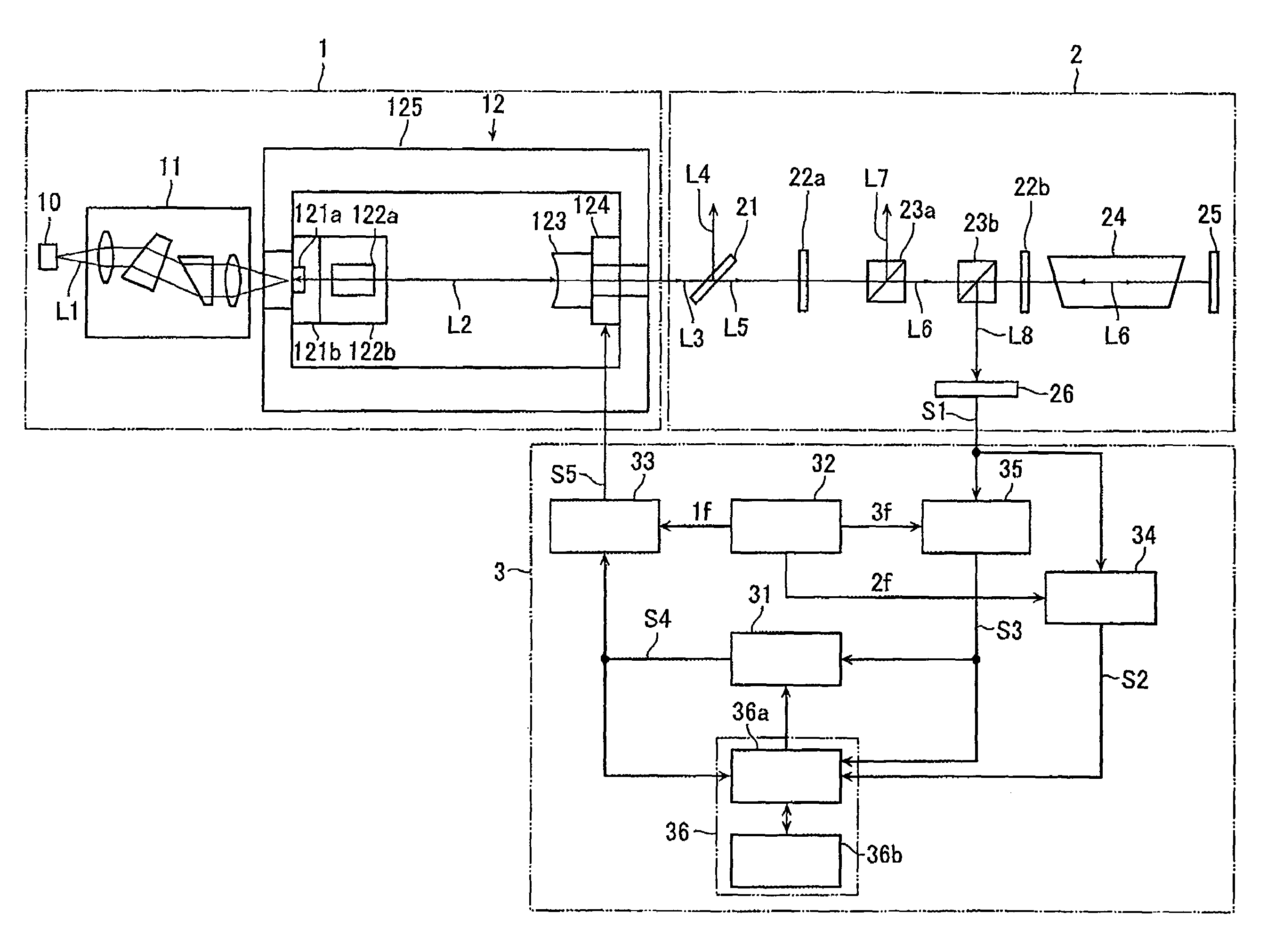
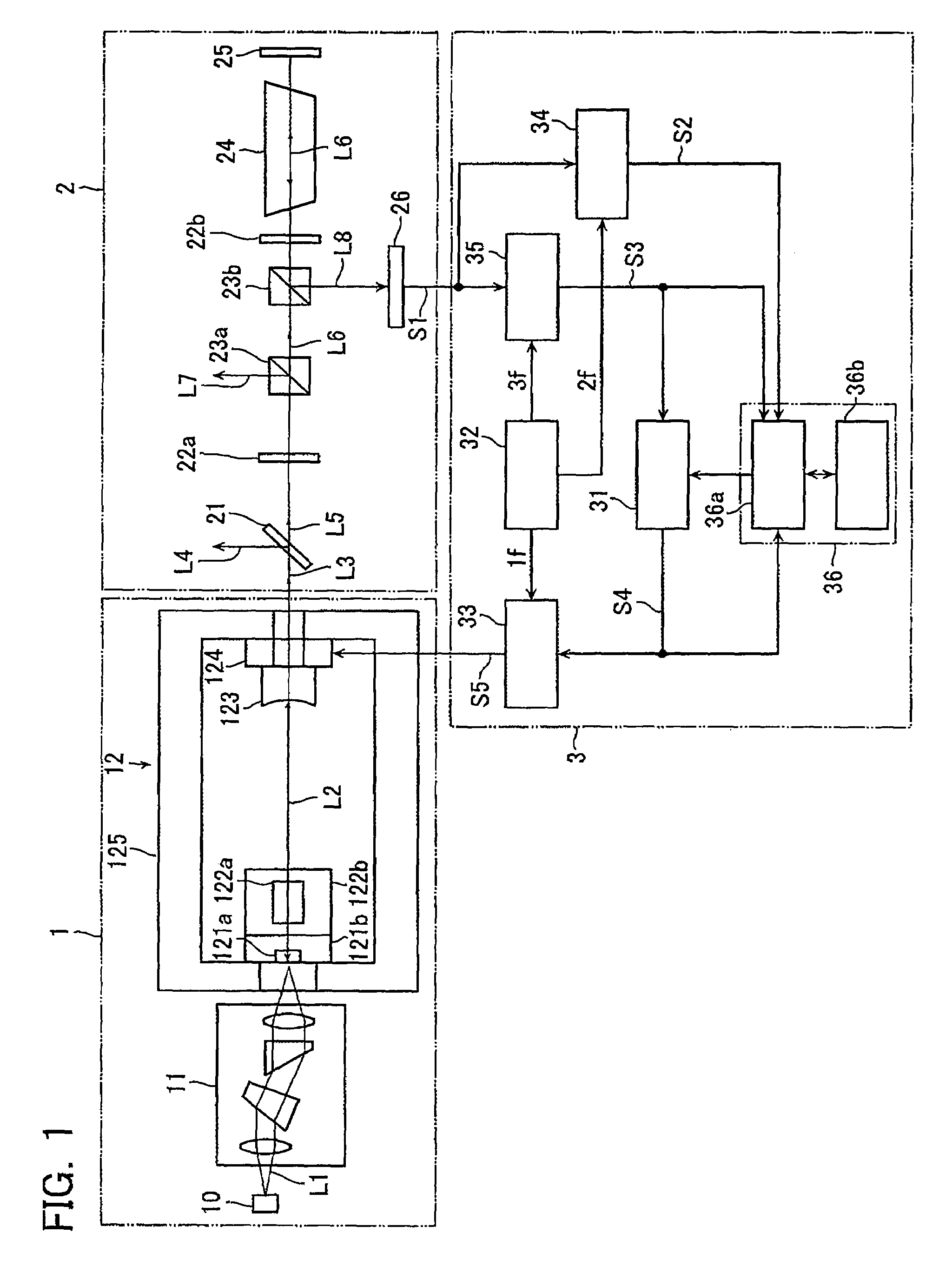
[0042]FIG. 1 is a schematic diagram that shows the configuration of the laser frequency stabilizing apparatus according to the first embodiment of the present invention. As shown in FIG. 1, the laser frequency stabilizing apparatus includes a laser generating section 1, a laser light detecting section 2 and a drive control section 3.

[0043]The laser generating section 1 includes: a pump semiconductor laser 10; a condensing system 11 configured from a plurality of optical elements; and a resonant wave generating section 12.

[0044]In the laser generating section 1, when a predetermined current is supplied to the pump semiconductor laser 10, laser light L1 with a wavelength of 808 nm is emitted. The emitted laser light L1 is condensed by the condensing system 11, and is guided to the res...

second embodiment

[0104]Next, the configuration of a laser frequency stabilizing apparatus according to a second embodiment of the present invention will now be described.

[0105]The laser frequency stabilizing apparatus according to the second embodiment has the configuration substantially similar to that in the first embodiment shown in FIG. 1. In the laser frequency stabilizing apparatus of the second embodiment, the actuator control section 31 and an overall movable range of the actuator 124 by the actuator drive section 33 are different from those in the first embodiment. Further, the function of the computer 36 (the automatic stabilizing section 36a) is different from that in the first embodiment. Moreover, a frequency filter for selecting a desired frequency set in the resonator is also different from that in the first embodiment. In this regard, in explanation for the second embodiment below, elements and processes identical with those of the first embodiment are assigned to the same reference ...


PUM


Abstract

A laser frequency stabilizing apparatus stabilizes an oscillation frequency of laser light by varying a resonator length on the basis of a saturated absorption line included in an optical output signal. The optical output signal is obtained by irradiating an absorption cell with the laser light. The laser frequency stabilizing apparatus includes: a light detecting section for detecting the optical output signal; a differential signal detecting section for detecting a differential signal of the optical light signal; an actuator for varying the resonator length; a drive section for driving the actuator; and a control section for controlling the drive section on the basis of the differential signal. The control section determines saturated absorption lines on the basis of an output of the differential signal, selects a specific saturated absorption line on the basis of the number of determined saturated absorption lines and a combination of the determined saturated absorption lines, and stabilizes the oscillation frequency of the laser light at the specific saturated absorption line.

Description

CROSS-REFERENCE TO RELATED APPLICATIONS[0001]This application is based upon and claims the benefit of priority from the prior Japanese Patent Application No. 2006-327218, filed on Dec. 4, 2006, the entire contents of which are incorporated herein by reference.BACKGROUND OF THE INVENTION[0002]1. Field of the Invention[0003]The present invention relates to a laser frequency stabilizing apparatus, a method and a computer program product for stabilizing a laser frequency by varying a resonator length on the basis of an optical output signal.[0004]2. Description of the Prior Art[0005]A wavelength of a solid laser of a 532 nm range based on continuous wave oscillation can be used as a length standard. In the continuous wave oscillation, an Nd:YAG crystal or the like that can be pumped by a semiconductor laser is used as a gain medium. As a matter of fact, in order to measure a length using a wavelength of laser light, the laser is required to have a single frequency. In other words; the l...

Claims


Application Information

Patent Timeline
Patent Type & Authority Patents(United States)
IPC IPC(8): H01S3/13
CPCH01S3/1392H01S3/09415H01S3/10069H01S3/109H01S3/1673H01S3/1398H01S3/1611H01S3/1305
Inventor NAKAGAWA, HIDEYUKI
Owner MITUTOYO CORP
Why Eureka
Try Eureka