
Turbocharger recirculation valve
a technology of recirculation valve and turbocharger, which is applied in the direction of air cleaners for fuel, combustion engines, machines/engines, etc., can solve the problems of engine to cease from operating completely, blockage of filters and/or ducts, and adverse effect on the locomotiv
- Summary
- Abstract
- Description
- Claims
- Application Information
AI Technical Summary
Benefits of technology
Problems solved by technology
Method used
Image

Examples
first embodiment
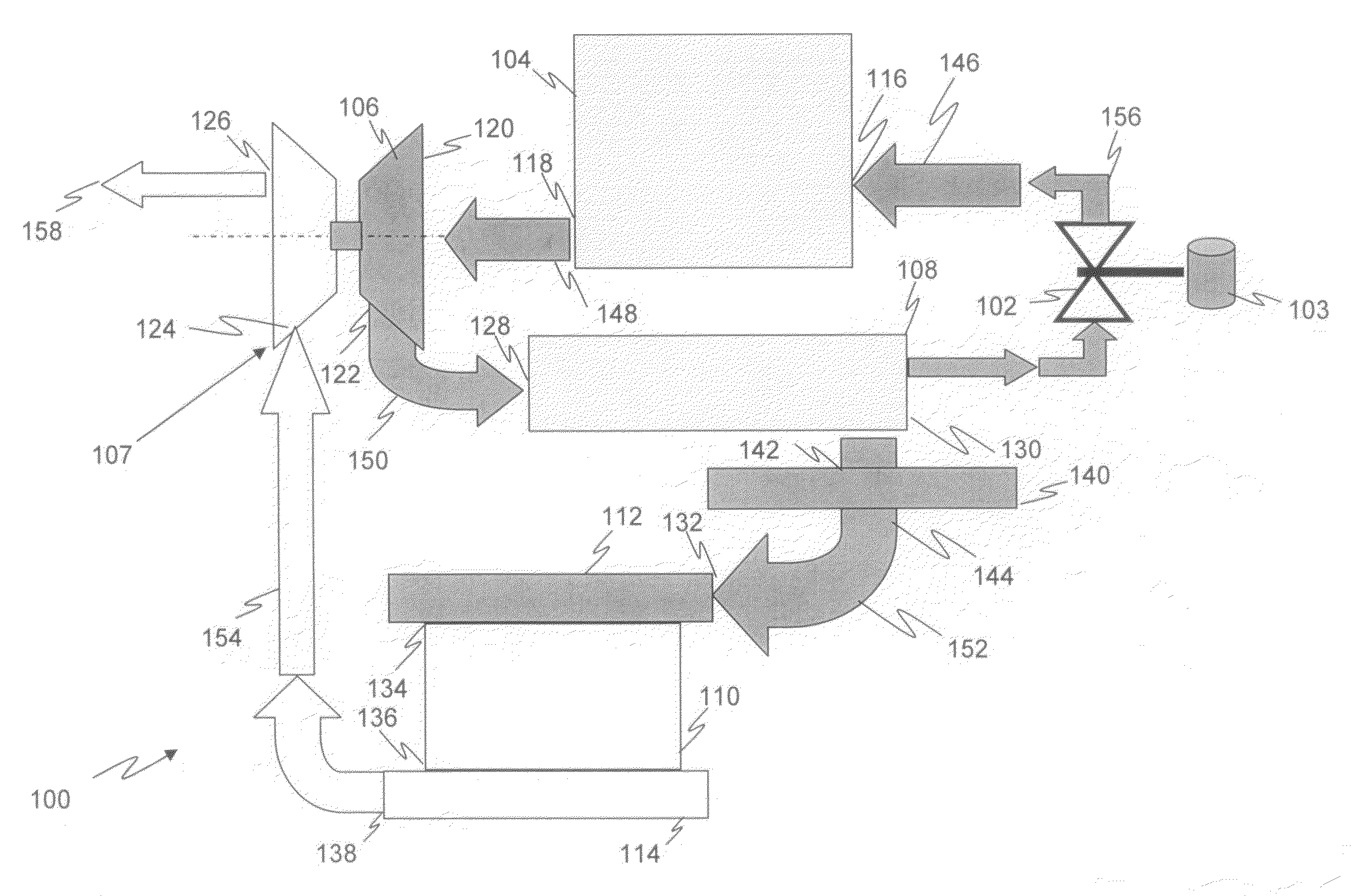
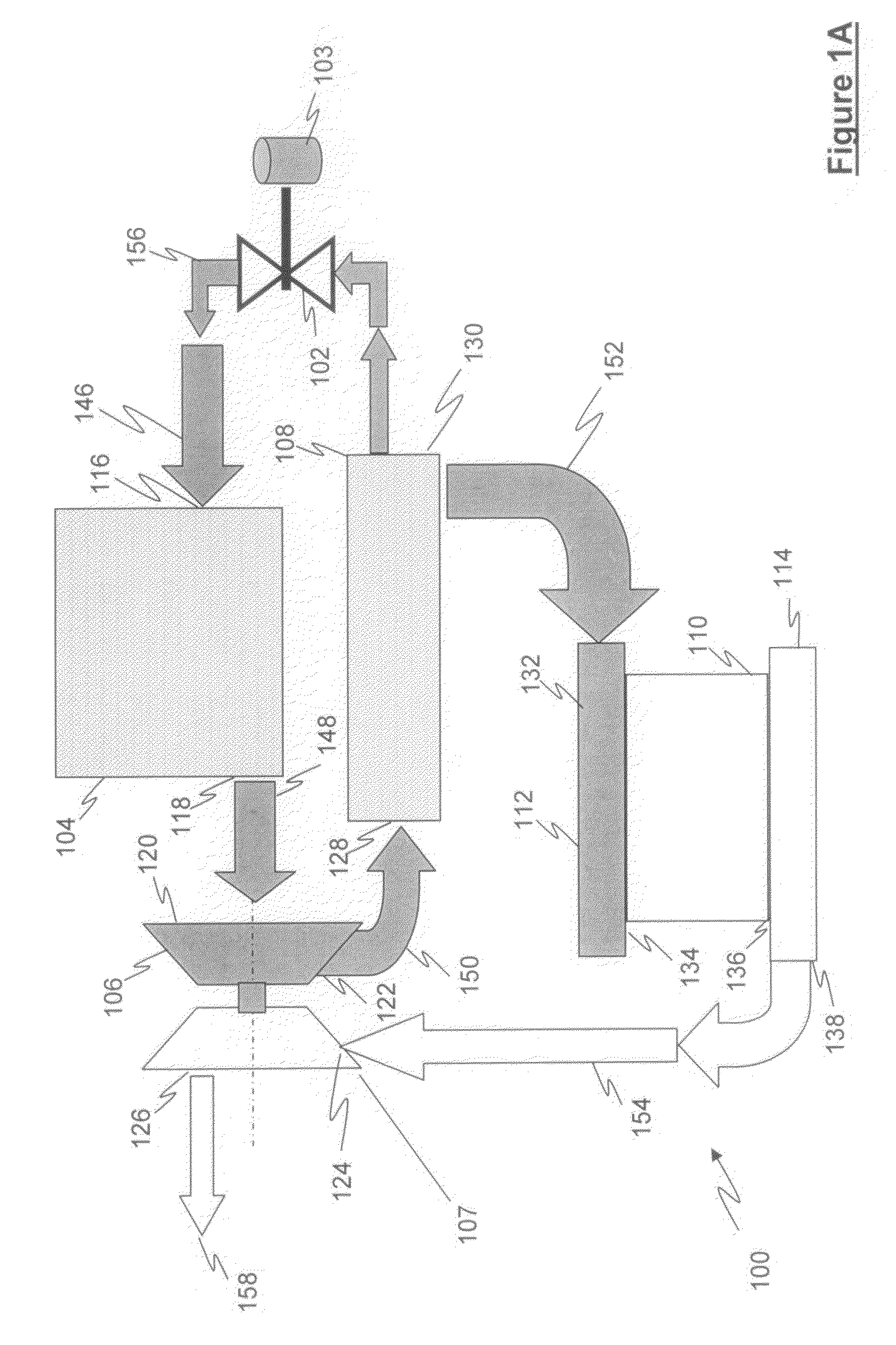
[0018]Referring to FIG. 1A, a schematic block diagram representing a locomotive turbocharger system 100 is shown and includes a turbocharger re-circulation valve 102 having a valve actuation device 103, an air filter box 104, a turbocharger compressor portion 106, a main intercooler device 108 and a locomotive engine 110, wherein locomotive engine 110 includes an intake manifold 112 and an exhaust manifold 114. Air filter box 104 includes an air inlet 116 and an air outlet 118, turbocharger compressor portion 106 includes a turbocharger compressor inlet 120, a turbocharger compressor outlet 122, a turbocharger turbine exhaust inlet 124 and a turbocharger turbine exhaust outlet 126. Main intercooler device 108 includes a main intercooler inlet 128 and a main intercooler outlet 130. Intake manifold 112 includes an intake inlet 132 and an intake outlet 134 and exhaust manifold 114 includes an exhaust inlet 136 and an exhaust outlet 138. In this embodiment, the main intercooler outlet 1...
second embodiment
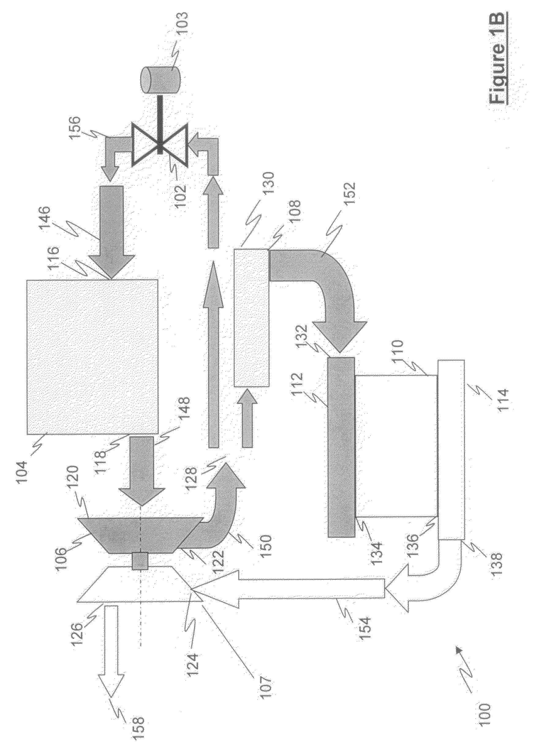
[0019]Referring to FIG. 1B, a schematic block diagram representing a locomotive turbocharger system 100 is shown and includes a turbocharger re-circulation valve 102 having a valve actuation device 103, an air filter box 104, a turbocharger compressor portion 106, a main intercooler device 108 and a locomotive engine 110, wherein locomotive engine 110 includes an intake manifold 112 and an exhaust manifold 114. Air filter box 104 includes an air inlet 116 and an air outlet 118, turbocharger compressor portion 106 includes a turbocharger compressor inlet 120, a turbocharger compressor outlet 122, a turbocharger turbine exhaust inlet 124 and a turbocharger turbine exhaust outlet 126. Main intercooler device 108 includes a main intercooler inlet 128 and a main intercooler outlet 130. Intake manifold 112 includes an intake inlet 132 and an intake outlet 134 and exhaust manifold 114 includes an exhaust inlet 136 and an exhaust outlet 138. In contrast to FIG. 1A, in this embodiment, the t...
PUM
 Abstract
Description
Claims
Application Information