Internal combustion engine controller

a technology of combustion engine and controller, which is applied in the direction of electric control, machines/engines, relays, etc., can solve the problems of circuit damage, adverse effect of valve-opening characteristics of injectors b>3/b>, and inability to drive circuits of large sizes, etc., to suppress the noise that affects the battery power supply, the effect of increasing the number of components

Active Publication Date: 2009-11-24
HITACHI ASTEMO LTD
View PDF14 Cites 31 Cited by
  • Summary
  • Abstract
  • Description
  • Claims
  • Application Information

AI Technical Summary

Benefits of technology

[0014]The present invention is intended to compensate for an overboost state of a voltage boost circuit in such a form as to suit particular driving conditions for an injector. The invention is also intended to prevent damage to the boost circuit if current regeneration occurs during execution of boosting and the overboost-compensating operation and the boost operation simultaneously occur to short-circuit a voltage boost capacitor and a power supply grounding element in the boost circuit.
[0015]In addition, in order to compensate for an overboost state, the invention is intended to provide an internal combustion engine controller having a voltage boost circuit, the controller being capable of minimizing the amount of heat occurring, the number of components to be added, and a noise level.
[0025]The above means makes the present invention offer a significant effect in that when current is returned from the boost voltage to the battery power supply in order to compensate for an overboost state of the boost voltage, since this overboost state is compensated for to fit the driving conditions of the injector, thermal damage to the boost circuit due to current regeneration by the injector during the boost operation is prevented. In addition, the invention works very effectively in that the boost coil used for the boost operation can also be used for current regeneration, in that an increase in the number of components required is suppressed, and in that the noise that effects the battery power supply is also suppressed.

Problems solved by technology

The above scheme that converts the energy into thermal energy can be used to simplify the driving circuit 200 possible, but is not suitable for a driving circuit of a large current since the current supply energy of the injector 3 is converted into thermal energy.
If this actually happens, the valve-opening characteristics of the injector 3 will be adversely affected.
In addition, if power supply short-circuiting or other trouble occurs in the injector, the boost voltage 100A is likely to exceed the withstand voltage of the driving element or voltage boost capacitor 111 of the boost circuit 100 and result in circuit damage.
However, once an overboost state has actually occurred, this state cannot be compensated for, so the above conventional technique has caused the situation that the arrival of the next injector supply current at the peak current level thereof has adverse effects upon the valve-opening characteristics of the injector.
If the foregoing current regeneration occurs during a voltage boost recovery period 406 that compensates for a decrease in the boost voltage, since the current regeneration can be used as the energy for voltage boost compensation, returning the regenerated current to the battery power supply will only turn out to be ineffective.
Unlike electric power-steering systems, therefore, the internal combustion engine controllers for driving an injector(s) do not allow control in which whether the regenerated current is to be returned from the voltage boost circuit 100 to the battery power supply is determined, depending upon whether current regeneration occurs.

Method used


Image

  • Internal combustion engine controller
  • Internal combustion engine controller
  • Internal combustion engine controller

Examples


first embodiment

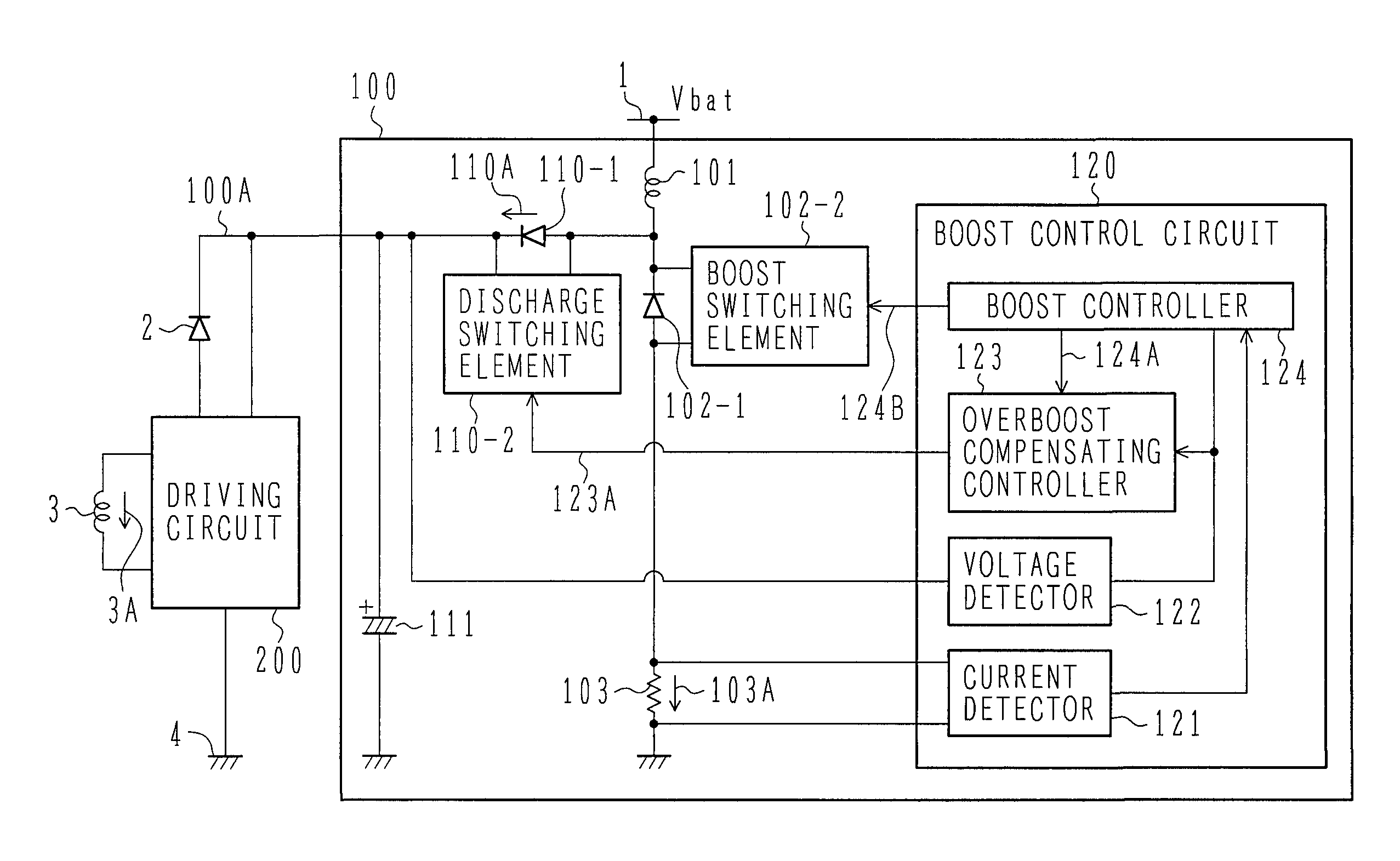
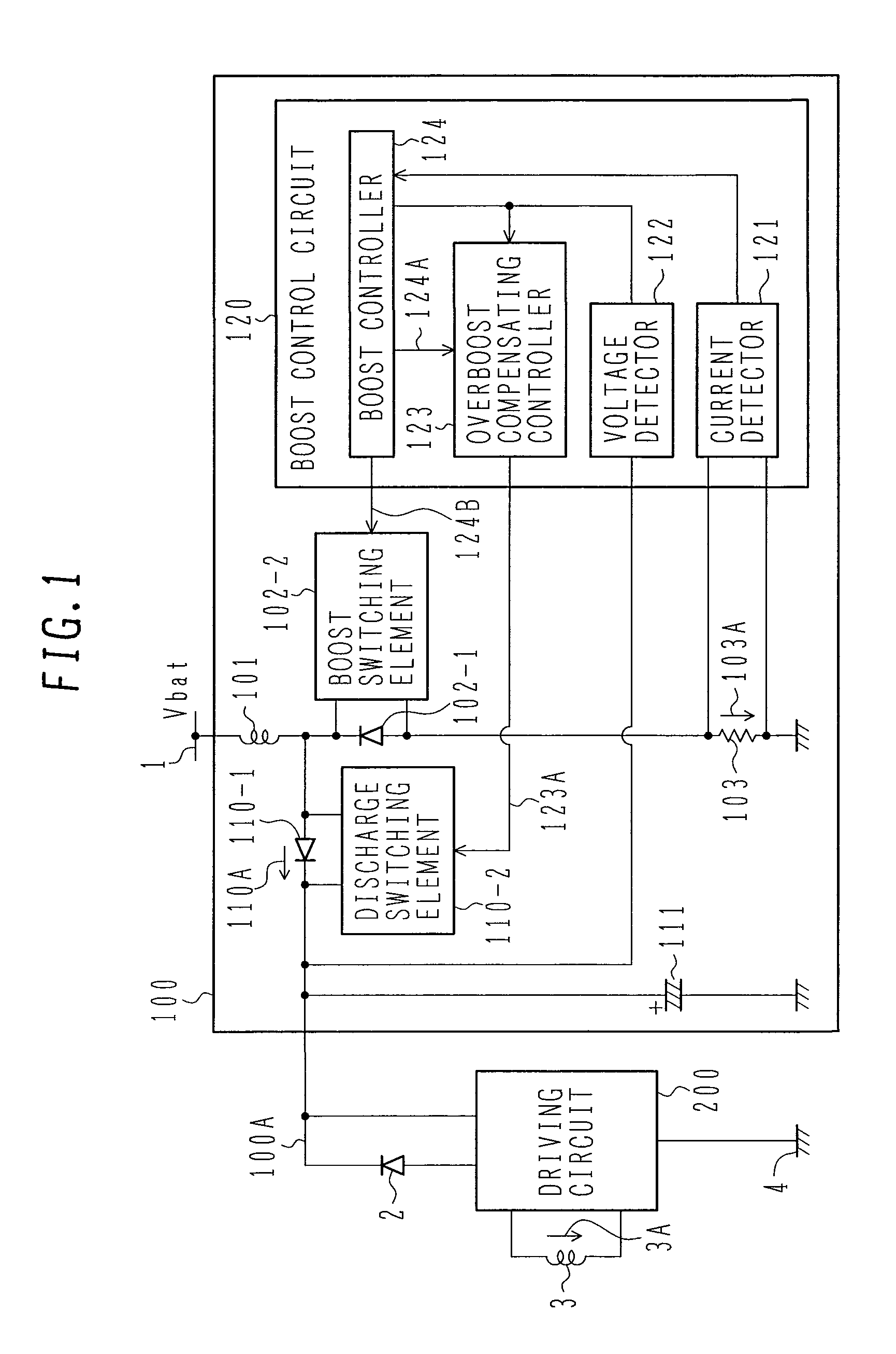
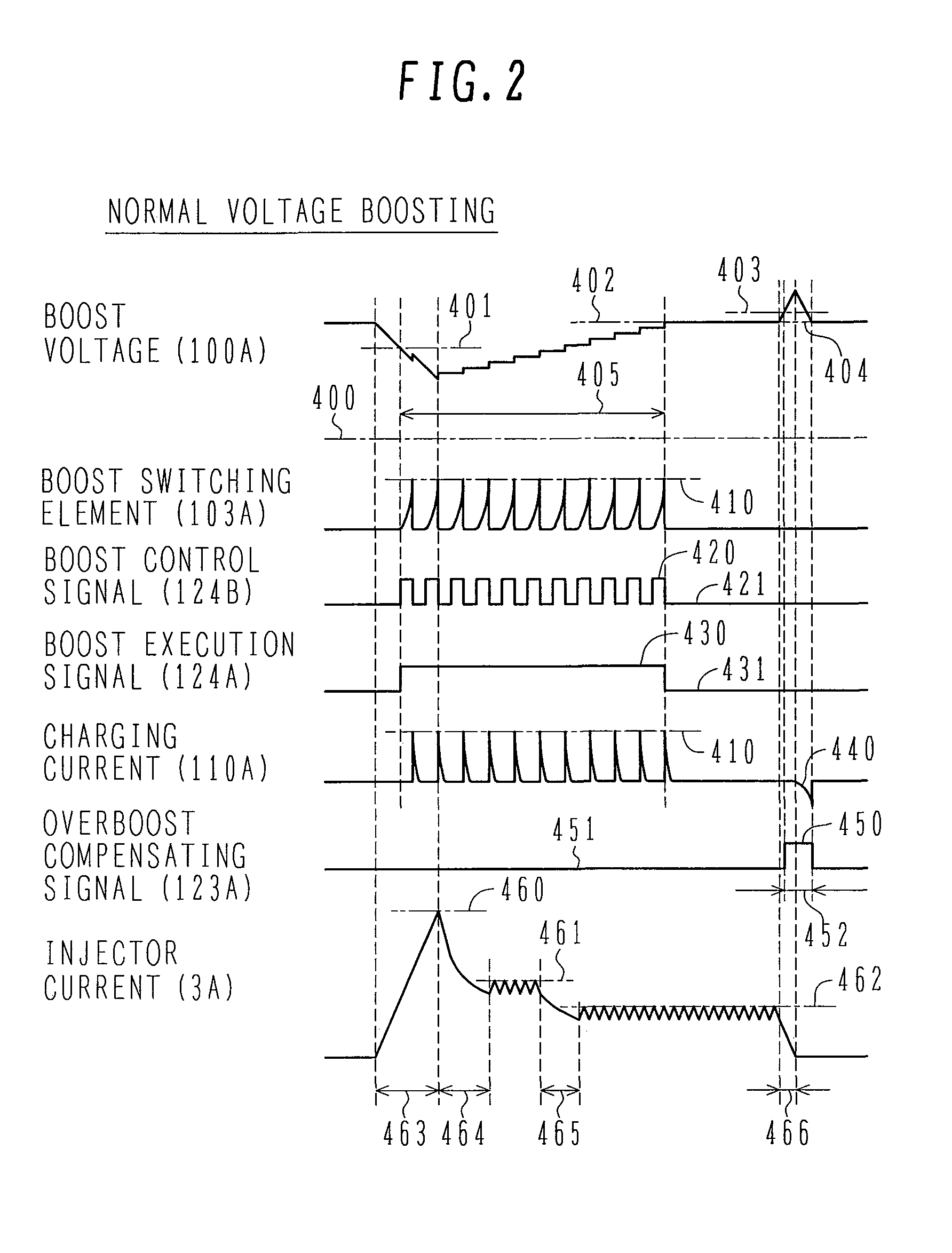
[0038]FIG. 1 shows a configuration of the first embodiment of an internal combustion engine controller according to the present invention. FIG. 2 shows an example of operating signal waveforms obtained under normal boost conditions in the first embodiment.

[0039]As shown in FIG. 1, the internal combustion engine controller according to the first embodiment includes a voltage boost circuit 100 powered from a battery power supply 1 via a power-grounding element 4 thereof, and a driving circuit 200 for driving an injector 3 by using a boost voltage 100A that has been increased to a high voltage by the boost circuit 100. The internal combustion engine controller also has a current-regenerating diode 2 to return a regenerated current of the injector 3 to the boost circuit 100 and make the boost circuit regenerate a new current. In addition, the internal combustion engine controller may have: input circuits for various sensors including an engine speed sensor; an arithmetic unit for comput...

second embodiment

[0052]FIG. 4 shows a configuration of the second embodiment of an internal combustion engine controller according to the present invention. FIG. 5 shows an example of operating signal waveforms obtained under normal boost conditions in the second embodiment.

[0053]As shown in FIG. 4, the internal combustion engine controller according to the second embodiment differs from the engine controller of the first embodiment in that a driving circuit 200 drives a second load device 5 different from the injector 3. However, as with the current regeneration by the injector 3, described in the first embodiment, a current regenerated by the second load device 5 is supplied to the injector-driving boost circuit 100 for regeneration, through the current-regenerating diode 6. The second load device 5, as with the injector 3, is driven using an inductance component, and examples of the second load device are described below. More specifically, the kind of second load device is not limited and the en...

third embodiment

[0063]FIG. 6 shows a configuration of the third embodiment of an internal combustion engine controller according to the present invention.

[0064]In the third embodiment, a control circuit 300 replaces the boost control circuit 120 used in the first or second embodiment. A case in which the boost control circuit in the first embodiment is replaced will be described below.

[0065]The control circuit 300 in the third embodiment is composed so that an arithmetic unit 303 operates in accordance with software stored in a memory 304, and so that even without special hardware, using a general-purpose microcomputer or the like makes it possible to implement a function equivalent to that of the boost control circuit 120 used in the first embodiment.

[0066]In addition to the memory 304 and the arithmetic unit 303, the control circuit 300 has an A / D converter 302 to convert voltages into digital signals, instead of the boost voltage detector and boost-switching current detector in the first embodim...


PUM


Abstract

In a voltage boost circuit for driving a fuel injector of an internal combustion engine, a high voltage developed in the voltage boost coil will be discharged into the battery power supply through the boost coil by electrically energizing a discharge switching element provided in parallel to the charging diode. If the overboost compensation overlaps a boost execution period, the end of the boost execution period will await starting of the overboost compensation.

Description

BACKGROUND OF THE INVENTION[0001]1. Field of the Invention[0002]The present invention relates generally to internal combustion engine controllers that drive loads using a high voltage obtained by boosting a battery voltage in an automobile, motorcycle, agricultural tractor, machine tool, marine engine, or other machines fueled with gasoline, a light oil, or the like. More particularly, the invention concerns an internal combustion engine controller suitable for driving an in-cylinder direct injection type of injector.[0003]2. Description of the Related Art[0004]Conventionally, in the automobiles, motorcycles, agricultural tractors, machine tools, marine engines, and other machines fueled with gasoline, light oil, or the like, injectors for injecting the fuel directly into cylinders are used to improve fuel efficiency and engine output. Such an injector is called the in-cylinder direct injection type of injector or simply called the direct injection (DI) type of injector. The engines...

Claims


Application Information

Patent Timeline
Patent Type & Authority Patents(United States)
IPC IPC(8): F02M51/00H01H47/32
CPCF02D41/20H02M1/32F02D2041/2003F02D2041/201F02D2041/2006
Inventor MAYUZUMI, TAKUYA
Owner HITACHI ASTEMO LTD
Why Eureka
Try Eureka