Linear motor and linear moving stage device

a technology of linear moving stage and linear motor, which is applied in the direction of photomechanical equipment, windings, instruments, etc., can solve the problems of difficult to achieve a thin body with this configuration, difficult to make thin linear moving stage devices, and high cost of moving magnet type linear motors, etc., to achieve reduced number of parts, such as coils and magnets, and eliminate the limit of mechanical strength due to attractive forces between magnets

Active Publication Date: 2009-11-24
TOSHIBA MASCH CO LTD
View PDF13 Cites 14 Cited by
  • Summary
  • Abstract
  • Description
  • Claims
  • Application Information

AI Technical Summary

Benefits of technology

[0023]According to the present invention, the number of parts, such as coils and magnets, can be reduced, and a limit in the mechanical strength caused by attractive forces between magnets can be eliminated, moreover, a thin linear motor can be provided by attaining sufficient thermal radiation of the coils and eliminating necessity of intensifying the magnetic field.
[0027]The linear motor of the present invention has advantages that the number of parts, such as coils and magnets, can be reduced, a limit in the mechanical strength due to attractive forces between magnets can be eliminated, and a thin body is attained by securing sufficient thermal radiation of the coils and eliminating the necessity of intensifying the magnetic field.
[0028]Also, in addition to the same advantages as those of the above linear motor, the linear moving stage device of the present invention has advantages that a distance from the mounting portion of the coils to the thrust applying point (a stage position) is made short and the thrust is transmitted directly to the stage to constrain generation of an incidental force, consequently, the control gain becomes high.

Problems solved by technology

Therefore, the movable magnet type linear motor is liable to be an expensive device.
But it is difficult to attain a thin body with this configuration because of the points (1) to (4) below.
From the above points (1) to (4), the linear motor 100 itself configured as shown in FIG. 10 is thick, so that when it is applied to a linear moving stage device, there is a disadvantage that the linear moving stage device is hard to be made thin due to the configuration.
Therefore, a decline of a control gain is caused, and a decline of stability of a stage speed, a decline of a settlement time when aligning the stage, and a decline of holding accuracy become disadvantageous.

Method used


Image

  • Linear motor and linear moving stage device
  • Linear motor and linear moving stage device
  • Linear motor and linear moving stage device

Examples


first embodiment

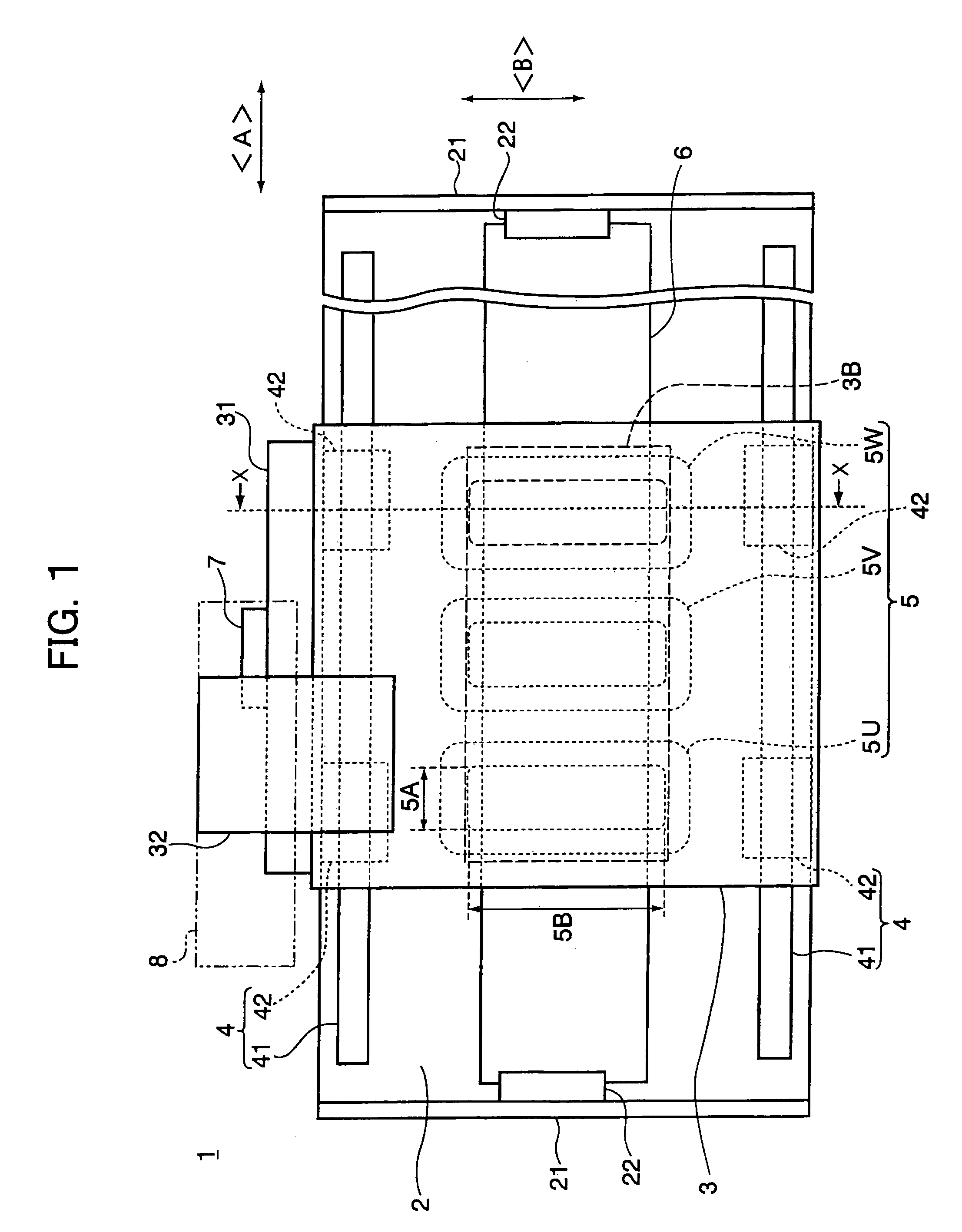
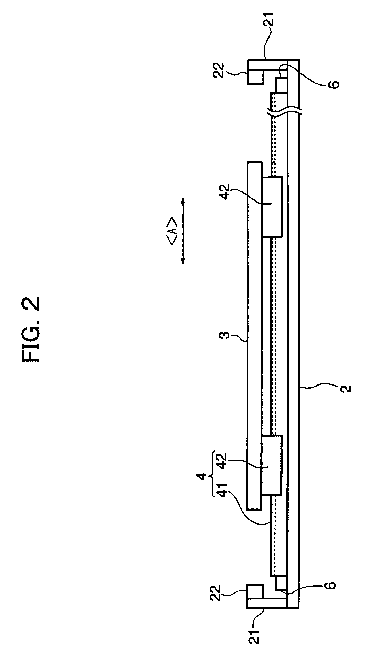
[0042]FIG. 1 is a plan view of a linear moving stage device according to a first embodiment. FIG. 2 is a view from the side in the stage moving direction A, and FIG. 3 is a sectional view along the line X-X in FIG. 1.

[0043]The linear moving stage device 1 includes a base 2, a stage 3 as a moving stage, a linear guide 4 provided between the base 2 and the stage 3, and a linear motor for giving thrust to the stage 3 to move linearly in a state of being supported on the base 2 by the linear guide 4. Note that the linear motor is generally composed of a coil, a permanent magnet and a yoke, etc. and the components will be explained later on.

[0044]As shown in FIG. 1 to FIG. 3, the base 2 has a flat plate shape longitudinal in the moving direction A of the stage 3. The base 2 in the present embodiment is made by a magnetic material, such as a cold rolled steel sheet (SPCC) and low carbon steel, and serves also as a yoke. Therefore, a thickness of the base 2 is regulated to a value required...

second embodiment

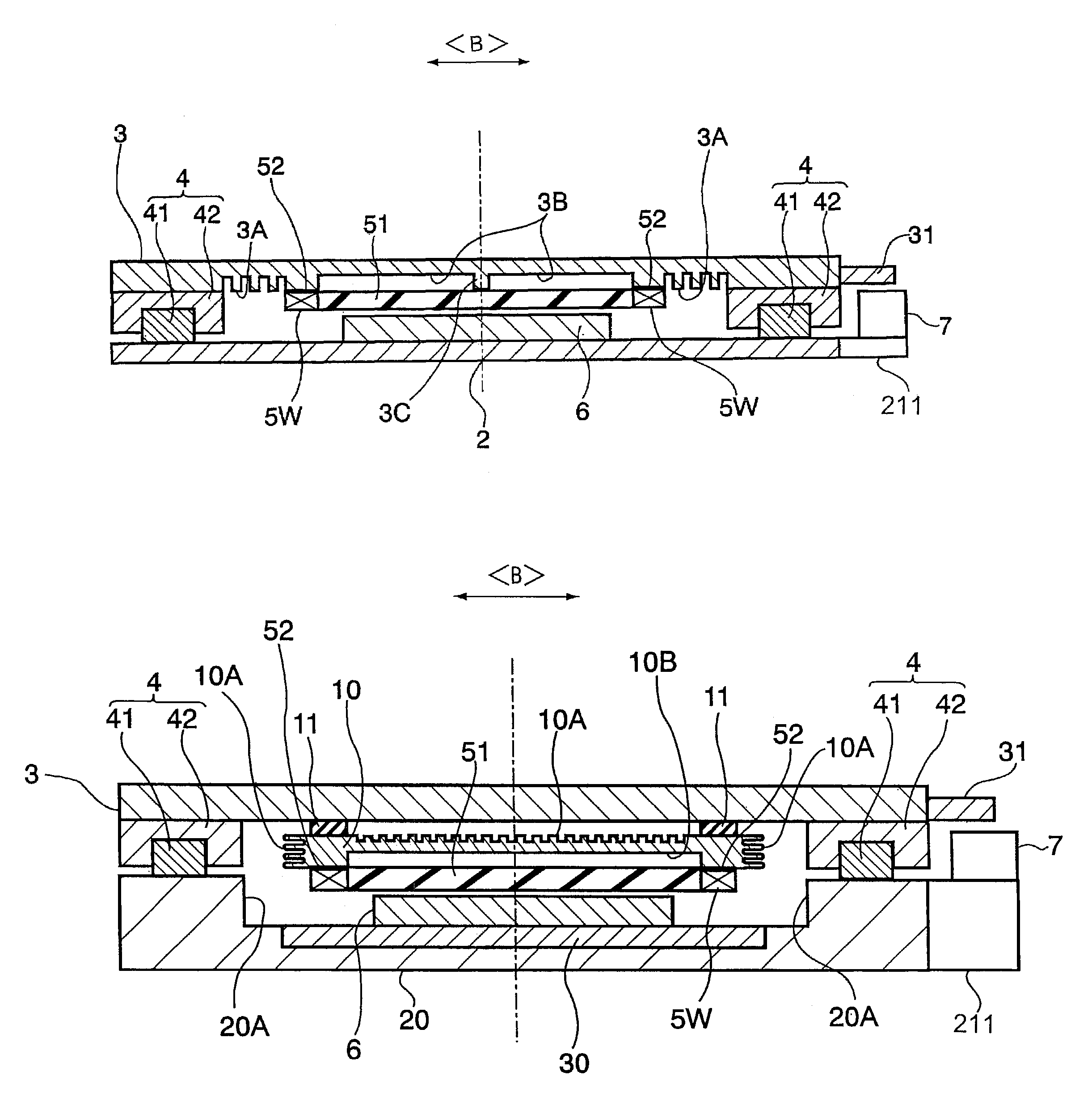
[0098]FIG. 5 is a plan view of a linear moving stage device according to a second embodiment. FIG. 6 is a view from the side in the stage moving direction, and FIG. 7 is a sectional view along the line X-X in FIG. 5.

[0099]What the linear moving stage device 1 of the present embodiment is largely different from that in the first embodiment is the shape of the base 20 and the heat radiating configuration of the yoke 30 and coils (particularly, the thermal radiation plate 10 is newly provided). This point will be explained in order below. Note that other parts are basically the same as those in the first embodiment, so that the same reference numbers are given in the drawings and the explanation will be omitted.

[0100]The base 20 in the present embodiment is composed of a light nonmagnetic material, such as aluminum, to trim weight of the entire body and formed by embedding the yoke 30 therein.

[0101]Because the coil thermal radiation plate 10 of the present embodiment has the thermal ra...

third embodiment

[0132]In the above first and second embodiments, the stage 3 or the thermal radiation plate 10 may be provided with a path of a cooling medium of a gas or liquid, for example, the air or water, etc. The present embodiment is the case of providing the path.

[0133]FIG. 8A is a sectional view of a linear moving stage device according to a third embodiment.

[0134]In the present embodiment, a tube composing a path 70 is provided inside the stage 3 or the thermal radiation plate 10. A position and the number of the path 70 may be freely determined. In the present embodiment, two paths 70 are provided near the part for fixing the coil 5 and one path 70 is provided near the center of the coil 5. Furthermore preferably, an outlet 71 of a cooling gas for cooling by blowing the gas directly to the coil 5 is provided to the path 70 at the center. The number per one coil and position of the cooling gas outlet 71 may be freely determined and, in the present embodiment, the cooling gas can be blown ...


PUM


Abstract

A linear motor for giving thrust to a movable unit capable of linearly moving freely in one direction with respect to a stator, comprising a plurality of permanent magnets arranged on the base side by lining up a positive pole and a negative pole in the one direction; and a plurality of flat shaped coils arranged along the arrangement direction of permanent magnets and fixed as armatures to said movable unit side so as to face the permanent magnets by leaving an electromagnetic gap; wherein a coil fixed surface on the stage side is provided a recessed portion for defining an air gap between the coil fixed surface and said coils.

Description

CROSS REFERENCES TO RELATED APPLICATIONS[0001]The present invention contains subject matter related to Japanese Patent Application JP 2004-258878 filed in the Japanese Patent Office on Sep. 6, 2004, the entire contents of which being incorporated herein by reference.BACKGROUND OF THE INVENTION[0002]1. Field of the Invention[0003]The present invention relates to a linear motor for giving thrust of free linear movement in one direction and a linear moving stage device capable of moving a stage by the provided linear motor.[0004]2. Description of the Related Art[0005]There are a movable magnet type and a movable coil type in a coreless linear motor of the related art. In the movable magnet type linear motor, coils have to be arranged on corresponding parts on the power supply side (primary side) over the almost all area of a movable stroke on the magnet side (secondary side). Therefore, the movable magnet type linear motor is liable to be an expensive device.[0006]On the other hand, th...

Claims


Application Information

Patent Timeline
Patent Type & Authority Patents(United States)
IPC IPC(8): H02K41/00
CPCG03F7/70758H02K3/47H02K5/18H02K9/00H02K41/03
Inventor MORIYAMA, TSUYOSHI
Owner TOSHIBA MASCH CO LTD
Why Eureka
Try Eureka