Information processing apparatus, method of controlling the same, information processing system, and computer-readable memory

Inactive Publication Date: 2009-11-24
CANON KK
View PDF13 Cites 0 Cited by
  • Summary
  • Abstract
  • Description
  • Claims
  • Application Information

AI Technical Summary

Benefits of technology

[0012]In view of the above, it is an object of the present invention to provide a technique of efficiently managing a data stream, such as a compressed image data, so as to reduce the amount of data transmitted via a network.

Problems solved by technology

However, although this lossless coding technique has the advantage that an image having certain image quality can be formed from a starting part of a file, the problem is that the compression ratio is as low as about 1:3.
In a computer network environment, although the processing capacity and the storage capacity of a computer can be easily improved, a network having a low transmission rate results in a great reduction in the overall processing capacity of the system.
If there is only one such a low-speed network, this network can cause a bottleneck.

Method used


Image

  • Information processing apparatus, method of controlling the same, information processing system, and computer-readable memory
  • Information processing apparatus, method of controlling the same, information processing system, and computer-readable memory
  • Information processing apparatus, method of controlling the same, information processing system, and computer-readable memory

Examples


first embodiment

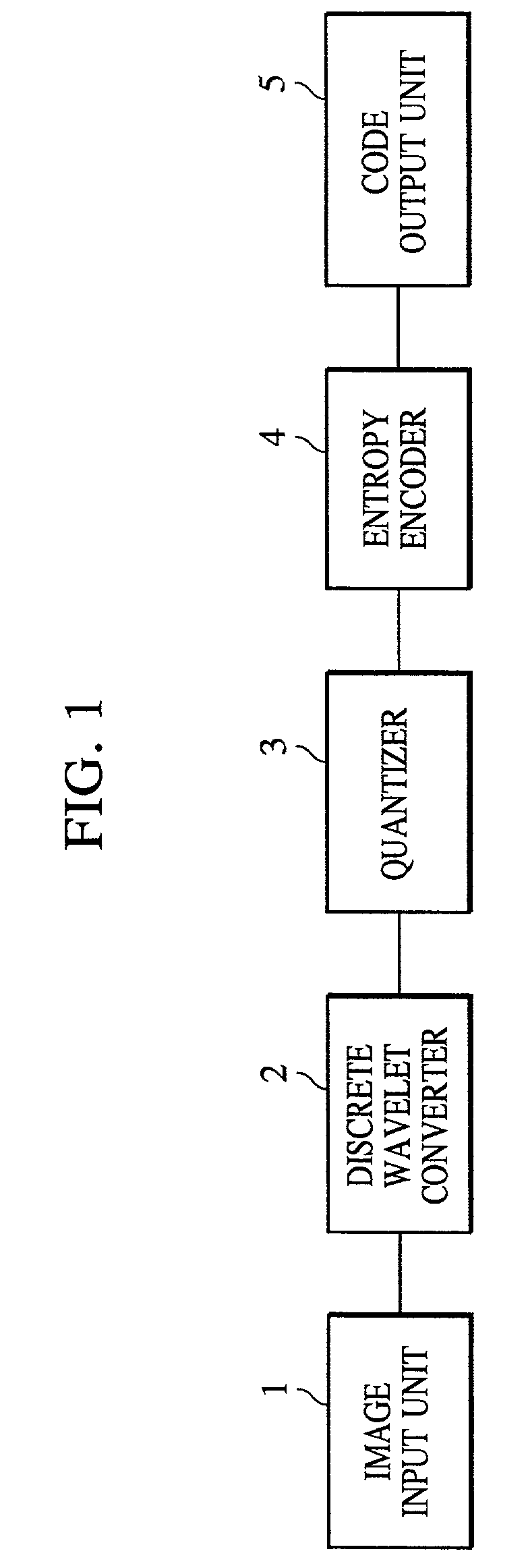
[0115]An image processing system according to a first embodiment of the present invention, in which the above-described coding algorithm based on, for example, JPEG2000 may be preferably employed, is described below with reference to FIG. 14.

[0116]FIG. 14 is a block diagram illustrating the image processing system according to the first embodiment of the present invention.

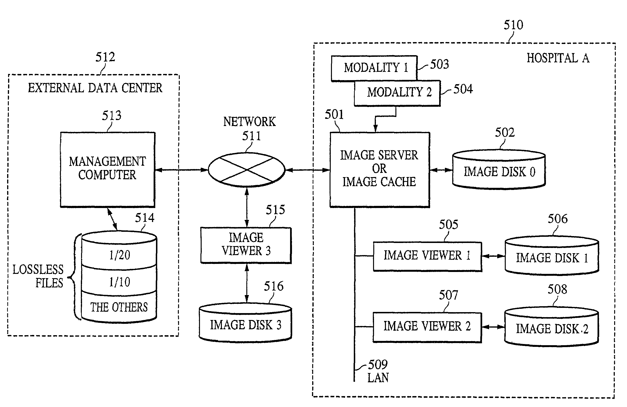
[0117]The image processing system according to the first embodiment of the present invention includes an external data center 512, which manages images such as medical images, a hospital A (510), and a terminal such as a personal computer having an image viewer-3 (515), all connected to each other via a network 511 such as the Internet.

[0118]In the hospital A (510), an image server (or image cache) 501 temporarily stores, on an image disk-0 (502), an image such as a medical image generated by a modality unit-1 (503) or a modality unit-2 (504) connected to the image server 5 via a network. Specific examples of the m...

second embodiment

[0207]In a second embodiment, an interrupted stream is stored in a storage unit of a diagnostic scheduler 547 and written into an external device (such as a storage unit of an image viewer, an image server, or a storage device) connected via a network.

[0208]FIG. 20 a block diagram of an image processing system according to the second embodiment of the present invention.

[0209]In this image processing system according to the second embodiment of the present invention, a hospital B (550) and a terminal such as a personal computer having an image viewer-7 (552) are connected to each other via a network 551 such as the Internet.

[0210]In the hospital B (550), images such as medical images generated by a modality unit-3 (543) or a modality unit-4 (544) connected to an image server (or an image cache) 501 are stored in a storage unit 542 of the image server 501.

[0211]An image outputted from the modality unit-3 (543) or the modality unit-4 (544) to the image server 501 may have already been ...


PUM


Abstract

In order to reduce the size of a data stream of image data transmitted via a network and to efficiently manage such a data stream, the image data is coded in a highly efficient fashion using a hierarchical coding algorithm, such as a wavelet transformation. When a data stream is being inputted, the data stream is analyzed and input of the data stream is interrupted in accordance with an analysis result. An interrupted stream is generated from the data stream that has already been inputted. The resultant interrupted stream is stored.

Description

BACKGROUND OF THE INVENTION[0001]1. Field of the Invention[0002]The present invention relates to an information processing apparatus capable of transmitting / receiving a data stream via a network, a method of controlling such an information processing apparatus, an information processing system, and a computer-readable memory.[0003]2. Description of the Related Art[0004]If a certain kind of fluorescent substance is irradiated with a radiation (such as X-rays, alpha rays, beta rays, gamma rays, electron rays, or ultraviolet rays), the energy of the radiation is partially stored in the fluorescent substance. If this fluorescent substance is excited by light, such as visible light, the fluorescent substance emits stimulated fluorescent light depending upon the stored energy. This type of fluorescent substance is called a storage fluorescent substance (stimulated fluorescent substance). It is known to temporarily record a radiation image of a subject such as a human body on a storage flu...

Claims


Application Information

Patent Timeline
IPC IPC(8): G06F15/16H03M7/30H04L29/02H04L29/06H04L29/08H04N7/24H04N19/00H04N19/102H04N19/134H04N19/172H04N19/186H04N19/34H04N19/63H04N19/86H04N19/90H04N19/91H04N21/2343H04N21/442H04N21/462H04N21/485
CPCH04L29/06H04N19/64H04N21/4621H04L67/2828H04N19/70H04N19/647H04N19/63H04N19/61H04N19/12H04N21/4508H04L67/2804H04L67/2819H04L67/288H04N19/10H04N19/115H04N19/146H04N21/234327H04N21/234354H04N21/442H04N21/4854H04L67/561H04L67/564H04L67/5651H04L9/40
Inventor TSUJII, OSAMUSATO, MAKOTO
Owner CANON KK
Why Eureka
Try Eureka