Multi-layer decoupling, sealing and drainage system

a multi-layer, sealing and drainage system technology, applied in the direction of layered products, building components, roof coverings, etc., can solve the problems of unavoidable moisture stress on ceramic paving, inability to avoid the diminished reliability of this type of paving, and costly repair work, etc., to achieve reliable and simple sealing, good conductance of liquid, and low flow resistance

Active Publication Date: 2009-12-01
BLANKE
View PDF22 Cites 10 Cited by
  • Summary
  • Abstract
  • Description
  • Claims
  • Application Information

AI Technical Summary

Benefits of technology

[0006]For this reason, it is the objective of the present invention to so develop a multilayer sealing and drainage system of this type such that in addition to an improvement of the drainage function in particular, it is also possible to achieve an improvement of the mechanical load-bearing capacity and anchoring to the tile layer.

Problems solved by technology

This method, which is satisfactory for interior applications, is problematic when ceramic paving is to be laid in an exterior area, because the effects of moisture and temperature on paving of this kind frequently result in the gradual destruction of the tiles or the base in which they are laid, and it becomes impossible to avoid the diminished reliability of this type of paving, with the result that costly repair work may be required.
The main problem encountered when laying ceramic paving in an exterior area is the unavoidable moisture stress on the ceramic paving, which is caused by rain water or by other moisture that is precipitated because of temperature variations in the environment.
Because the thin-bed method is used, it is as good as unavoidable that cavities will form beneath tiles, and in time these cavities will be filled with the water that has penetrated as described above, thereby causing a permanent moisture stress, on the one hand on the ceramic paving and on the other hand on the substratum.
Because of these unavoidable cavities, it is possible, in particular during the cold time of the year, that the water that accumulates within the cavities in the thin-bed mortar will freeze and expand, thereby causing the ceramic paving to separate.
In the same way, the water that accumulates within the cavities can generate a great deal of steam pressure as a result of solar radiation on ceramic paving laid in an exterior area and, in the case of glazed tiles, for example, this can cause the tiles to shatter.
This results in similar shattering of the ceramic surface.
Furthermore, the accumulated water can cause chalk to be released from the joint mortar and from the thin-bed mortar, and this can result in efflorescence from the joints.
In addition, the tile adhesive in the hollow spaces beneath the ceramic paving, which is usually processed as plastic mortar, can become superficially dissolved and thereby lose its strength.
In addition to the foregoing, it is difficult to control the crack behaviour of the ceramic paving and of the substratum because of the very different coefficients of expansion of the substratum, the thin-bed mortar, and the ceramic paving, which are brought about by the very high temperature differences between the high temperatures caused by solar radiation and the low temperatures caused by frost that occur in the exterior area.
Furthermore, substrata of this kind beneath ceramic paving also bring about deliberate decoupling between the ceramic paving and substratum since, for example, stress cracks or loading cracks can frequently occur because of the different rates of thermal expansion or elasticity between the ceramic paving and the substratum.
It is true that, within certain limits, this layered construction permits moisture that has penetrated to drain out of the substratum of a tile layer; however, the mechanical load-bearing capacity of a layered, construction of this kind is unsatisfactory since embedding the uppermost non-woven layer in the tile mortar does not permit adequate anchoring or reinforcing function.

Method used


Image

  • Multi-layer decoupling, sealing and drainage system
  • Multi-layer decoupling, sealing and drainage system
  • Multi-layer decoupling, sealing and drainage system

Examples


Embodiment Construction

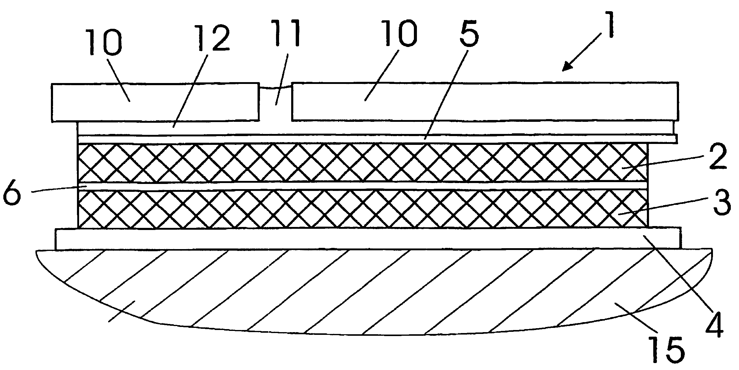
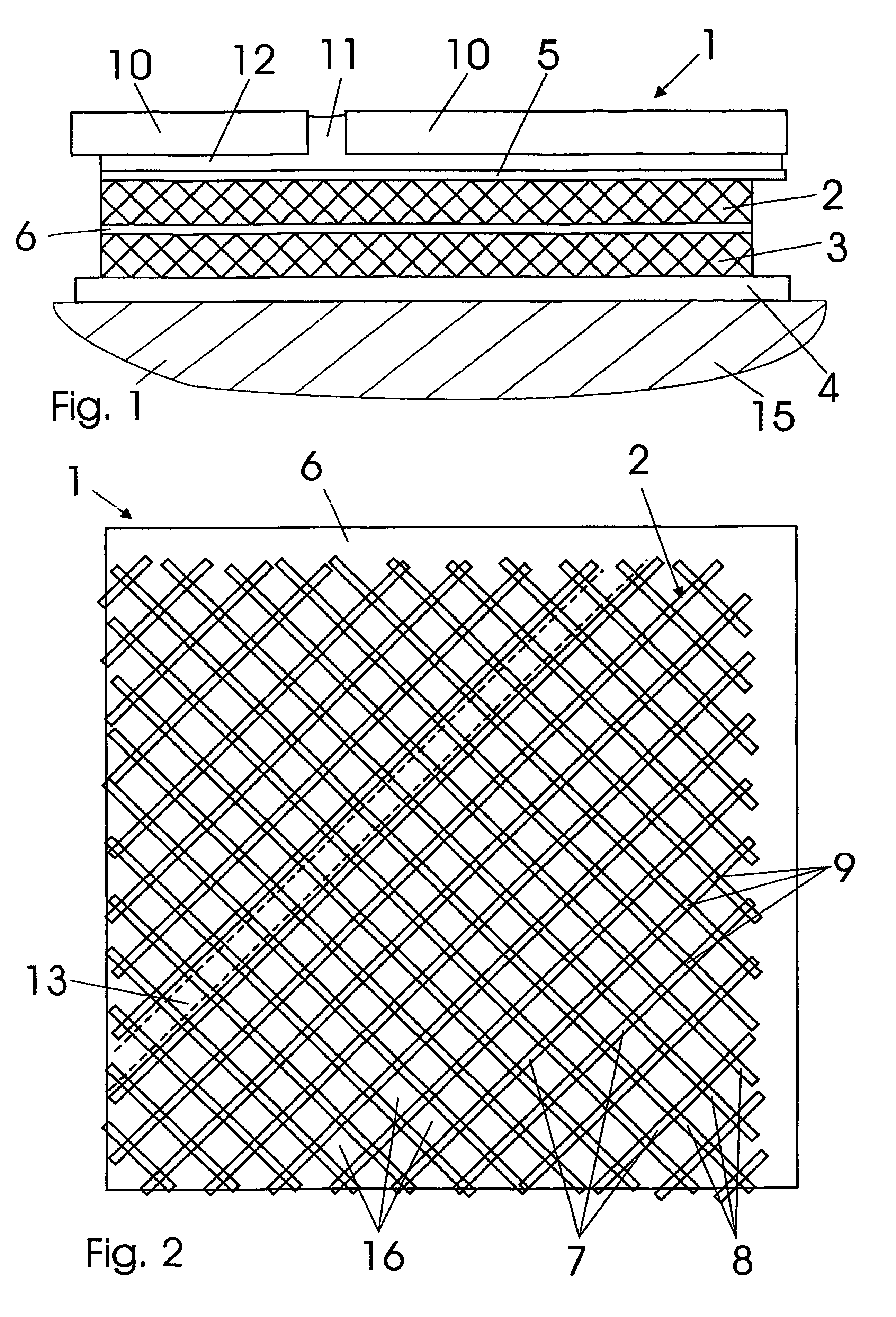
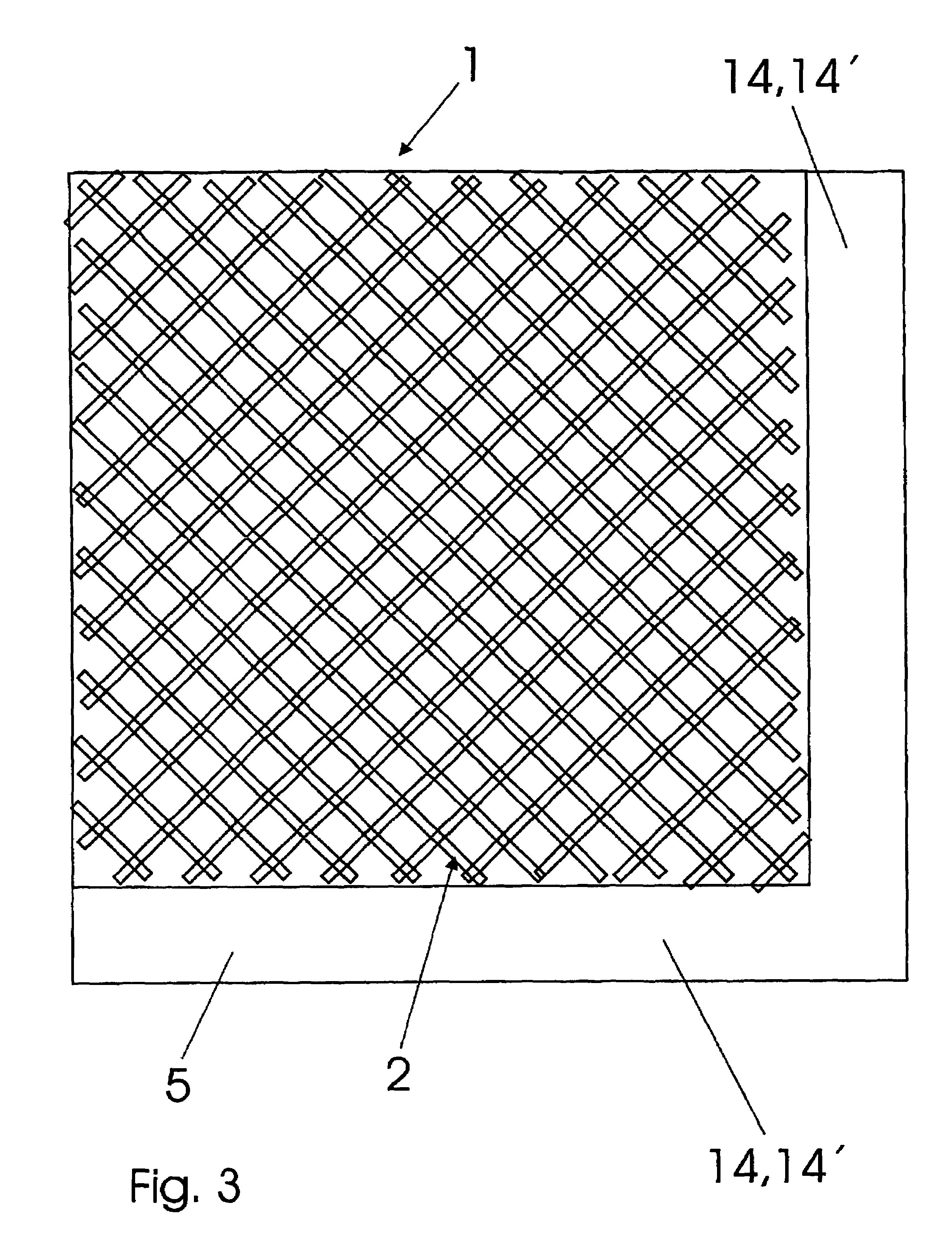
[0030]FIG. 1 is a cross sectional side view that shows the layered structure of a multilayer decoupling, sealing, and drainage system 1. FIG. 2 is a cross sectional plan view at the level of a non-woven layer 6, and FIG. 3 is a plan view of the decoupling, sealing and drainage system 1, in cross section along the reinforcing layer 5. In FIG. 1, the decoupling, sealing, and drainage system 1 according to one embodiment of the present invention is shown installed on a substratum 15, for instance in a cement screed or the like. Tile paving made up of tiles 10 can be seen above the decoupling, sealing, and drainage system 1 and this is laid in tile mortar 12 by the thin-bed method. The joints 11 between the individual tiles 10 are similarly filled with tile mortar 12.

[0031]The decoupling, sealing, and drainage system 1 consists of a sealing layer 4 that is applied to the substratum 15 and can be formed, for example, from bitumen or polyethylene and can be laid as a strip of predetermine...


PUM

PropertyMeasurementUnit
thicknessaaaaaaaaaa
thicknessaaaaaaaaaa
thicknessaaaaaaaaaa

Abstract

The invention relates to a multi-layer sealing and drainage system (1), in particular for the laying of ceramic paving (10) according to a thin-bed method (12). Said system comprises a layered construction containing, from the base upwards, a drainage layer (3) that is configured from a first lattice-type structural element and comprises drainage regions (13) that are formed between the lattice structures of said element, a liquid-permeable nonwoven layer (6), an anchorage layer (2) that is configured from a second lattice-type structural element and that is used to hold a filler material (12), which is to be incorporated into the upper face of the sealing and drainage system (1) and which is plastic during processing and subsequently cures, in addition to a reinforcement layer (5), which is fixed, at least in some sections, to the anchorage layer (2). The system can also comprise a sealing layer below the drainage layer.

Description

FIELD OF THE INVENTION[0001]The present invention relates to a multilayer decoupling and sealing system, in particular for laying ceramic paving by using a thin-bed method.BACKGROUND[0002]Today, ceramic paving, in particular ceramic tiles, is usually laid using the so-called thin-bed method, in which the ceramic paving is laid in a thin, adhesive layer of tile mortar. This method, which is satisfactory for interior applications, is problematic when ceramic paving is to be laid in an exterior area, because the effects of moisture and temperature on paving of this kind frequently result in the gradual destruction of the tiles or the base in which they are laid, and it becomes impossible to avoid the diminished reliability of this type of paving, with the result that costly repair work may be required.[0003]The main problem encountered when laying ceramic paving in an exterior area is the unavoidable moisture stress on the ceramic paving, which is caused by rain water or by other moist...

Claims


Application Information

Patent Timeline
Patent Type & Authority Patents(United States)
IPC IPC(8): E04F13/08B32B3/24E04D11/02E04F15/02E04F15/08E04F15/18E04F17/00
CPCB32B3/266E04F15/02E04F17/00E04F15/18E04F15/08E04F15/0215E04F15/187E04F15/186E04F15/182E04F15/183B32B9/04B32B2307/7246B32B7/12B32B2307/726B32B2307/102B32B7/05
Inventor THRONICKE, SANDRO GERDBLANKE, PETER WILHELM
Owner BLANKE
Why Eureka
Try Eureka