Constant-temperature-difference flow sensor, and integrated flow, temperature, and pressure sensor

a flow sensor and constant temperature difference technology, applied in the direction of measurement devices, instruments, structural/machine measurement, etc., can solve the problems of affecting the flow, affecting the flow, and affecting the flow,

Inactive Publication Date: 2009-12-01
GENERAL ELECTRIC CO +1
View PDF7 Cites 55 Cited by
  • Summary
  • Abstract
  • Description
  • Claims
  • Application Information

AI Technical Summary

Benefits of technology

[0013]In one very advantageous embodiment, the integrated sensor is further integrated with a remotely controllable valve. In this embodiment, a controllable valve having a controllable flow channel is connected by a further fluid path to the flow path of the integrated sensor. The controllable valve is located within the same body as that in which the integrated sensor is located. This particular embodiment is most advantageously used in a system further including a control processor at a location remote from the body of the integrated sensor, and coupled thereto by way of the transmission path, for correlating valve state with fluid flow for one of (a) verifying operation of an element of the integrated sensor and (b) verifying the integrity of fluid paths to which the integrated sensor is connected.

Problems solved by technology

The costs associated with maintaining a large crew are disadvantageous, and such costs include the costs associated with paying wages, maintaining the crew member in terms of food and life support (bathrooms, hot water, and the like), and also includes the costs of training the crew member for the particular job.
The problem is particularly acute in war vessels, as a relatively large crew must be maintained in order to have the resources to perform battle damage repair and recovery.
The rotating-propeller is very accurate, but may degrade over time as a function of corrosion and deposits, and may fail catastrophically in the presence of large debris.
The differential-pressure type of flow sensor requires an obstructing aperture or change of geometry of the flow path, which is very undesirable, and when the application requires many such sensors to be cascaded, may substantially impede the flow.
Also, the small pressure changes attributable to relatively large apertures may undesirably introduce noise into the measurement.
Additionally, in a vehicle which has vertical motion, the vertical acceleration tends to add to the gravitational force acting on the ball, and will tend to affect the reading, and therefore the accuracy.
The vane deflection type of flow sensor obstructs the flow with the vane, and is not known for their accuracy.
The ultrasonic type of flow sensor does not necessarily impede the flow, but is expensive, and may not be suitable for use in a noisy environment, or in an environment in which many such sensors are in use, so that the ultrasonic signals of one affect the others in the same flow path.
The hot-wire anemometer is not known for use in fluids other than air, would not work in a conductive fluid, and the thin wire would be subject to breakage by circulating debris in some applications.

Method used


Image

  • Constant-temperature-difference flow sensor, and integrated flow, temperature, and pressure sensor
  • Constant-temperature-difference flow sensor, and integrated flow, temperature, and pressure sensor
  • Constant-temperature-difference flow sensor, and integrated flow, temperature, and pressure sensor

Examples


Embodiment Construction

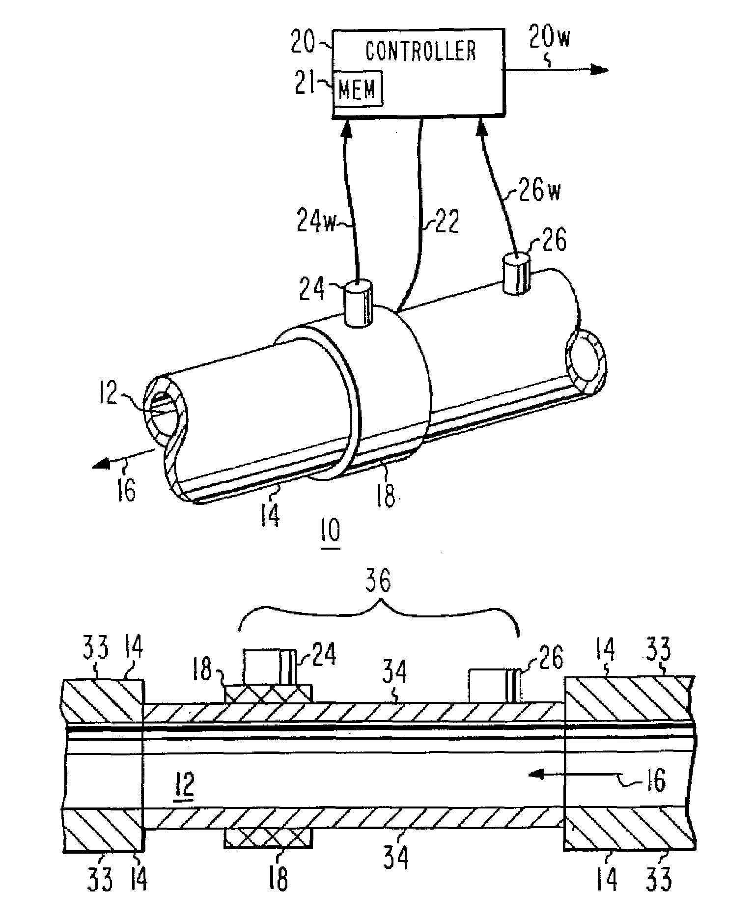
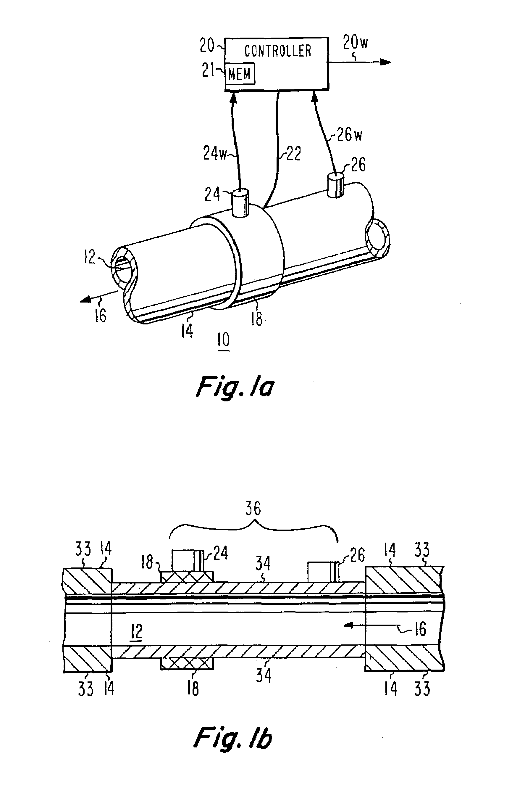
[0026]In FIG. 1a, a sensor 10 includes a fluid path 12 in the form of a round pipe 14 through which fluid flows in a direction designated by an arrow 16. Sensor 10 supports an annular peripheral electrical heating element or heater 18. A flow of electrical energy or power is applied to heater 18 from a controller 20 by way of a set 22 of wires. A temperature sensor 24 is coupled to heating element 18, for producing a signal representing the temperature of the heating element. The temperature-representative signal is applied to controller 20 by way of a set of wires 24w. Controller 20 includes a memory (Mem) designated 21. A further temperature sensor 26 is mounted to pipe 14 at a location upstream from heating element 18, for sensing the temperature of the fluid flowing in pipe 14, and for generating a signal representing the temperature of the fluid. The signal representing the temperature of the fluid is applied over a set of wires 26w to controller 20.

[0027]FIG. 1b is a represent...


PUM


Abstract

An integrated sensor for automated systems includes a flow sensor, a temperature sensor, a pressure sensor, and a network interface. In a particular embodiment of the invention, the flow sensor includes a temperature sensor (26) which determines the temperature of the fluid flowing in a flow path (12). A heater (18) is coupled to the flow path, and is energized by a controller (20) with sufficient electrical power to raise the temperature of the heater above the measured fluid temperature by a fixed temperature difference. In order to aid in determining the temperature difference, a sensor (24) may be associated with the heater (18). The amount of power required to maintain the temperature difference is a measure of the flow velocity. The volumetric flow rate is the product of the flow velocity multiplied by the area of the flow sensor. The mass flow rate is the product of the volumetric flow rate multiplied by the mass density of the fluid. In a particular embodiment, the pressure sensor is ratiometric.

Description

FIELD OF THE INVENTION[0001]This invention relates to integrated flow, temperature and pressure sensors for fluids, and more particularly to such sensors in which a heater is maintained at a constant temperature differential above the temperature of the flowing fluid, a temperature sensor which coacts with the heater to provide flow information, a ratiometric pressure sensor provides fluid pressure, and a controller processes the individual sensor signals and communicates digitally over a digital transmission path.BACKGROUND OF THE INVENTION[0002]Modern ships employ crew members whose function is to monitor various parts of the vessel, and to operate equipment such as hoists, radar, bridge equipment, and to monitor and control valves located throughout the ship. The costs associated with maintaining a large crew are disadvantageous, and such costs include the costs associated with paying wages, maintaining the crew member in terms of food and life support (bathrooms, hot water, and ...

Claims


Application Information

Patent Timeline
Patent Type & Authority Patents(United States)
IPC IPC(8): G01F1/68
CPCG01M3/2807G01F1/6847
Inventor HOYLE, SCOTT BAXTERBERKCAN, ERTUGRULMCSWEENEY, MICHAEL ANTHONY
Owner GENERAL ELECTRIC CO
Why Eureka
Try Eureka