Re-oriented over fire air ports for reduction of NOx production from pulverized coal-fired burners

a technology of pulverized coal and burners, which is applied in the direction of fluidised bed combustion apparatus, combustion types, lighting and heating apparatus, etc., can solve the problems of reducing the benefit, occupying additional space in the upper furnace region, and displaced combustion to a region. , to achieve the effect of reducing nox in pulverized coal-fired furnaces and boilers

Inactive Publication Date: 2009-12-01
POLY MED +1
View PDF5 Cites 6 Cited by
  • Summary
  • Abstract
  • Description
  • Claims
  • Application Information

AI Technical Summary

Benefits of technology

[0014]It is an object of the present invention to provide a novel arrangement of OFA ports for further reducing NOx in pulverized coal-fired furnaces and boilers.
[0015]Another object of the invention is to provide an OFA port configuration for improved residence time between the burners and OFA ports.
[0016]Accordingly, a furnace or boiler including the OFA system of the invention is provided in which over fire air ports are provided on the furnace enclosure sidewalls for introducing OFA transverse to the burner flame paths. An OFA port is optimally positioned to inject over fire air at each burner level flame path and provide good residence time. The air flow rate, air jet velocity and momentum are adjusted to produce maximum effectiveness and over fire air penetration into the furnace enclosure at the desired burner level flame path while avoiding increasing NOx production due to excess oxygen being present in higher burner levels.

Problems solved by technology

This results from combustion being displaced to a region of the furnace or boiler beyond the OFA ports.
Prematurely adding over fire air will negate the benefit as the desired chemistry is disrupted.
The effect on reduction of NOx is not consistent due to differences in residence time between the burners and the OFA ports, and differences in gas flow through the furnace resulting in different interactions of the OFA and flame paths, among other factors.
However, this also requires additional space in the upper furnace region of the enclosure 10.
Thus, increasing the OFA port 20 spacing requires a taller furnace enclosure 10, thereby increasing the costs and making a bigger building.

Method used


Image

  • Re-oriented over fire air ports for reduction of NOx production from pulverized coal-fired burners
  • Re-oriented over fire air ports for reduction of NOx production from pulverized coal-fired burners
  • Re-oriented over fire air ports for reduction of NOx production from pulverized coal-fired burners

Examples


Embodiment Construction

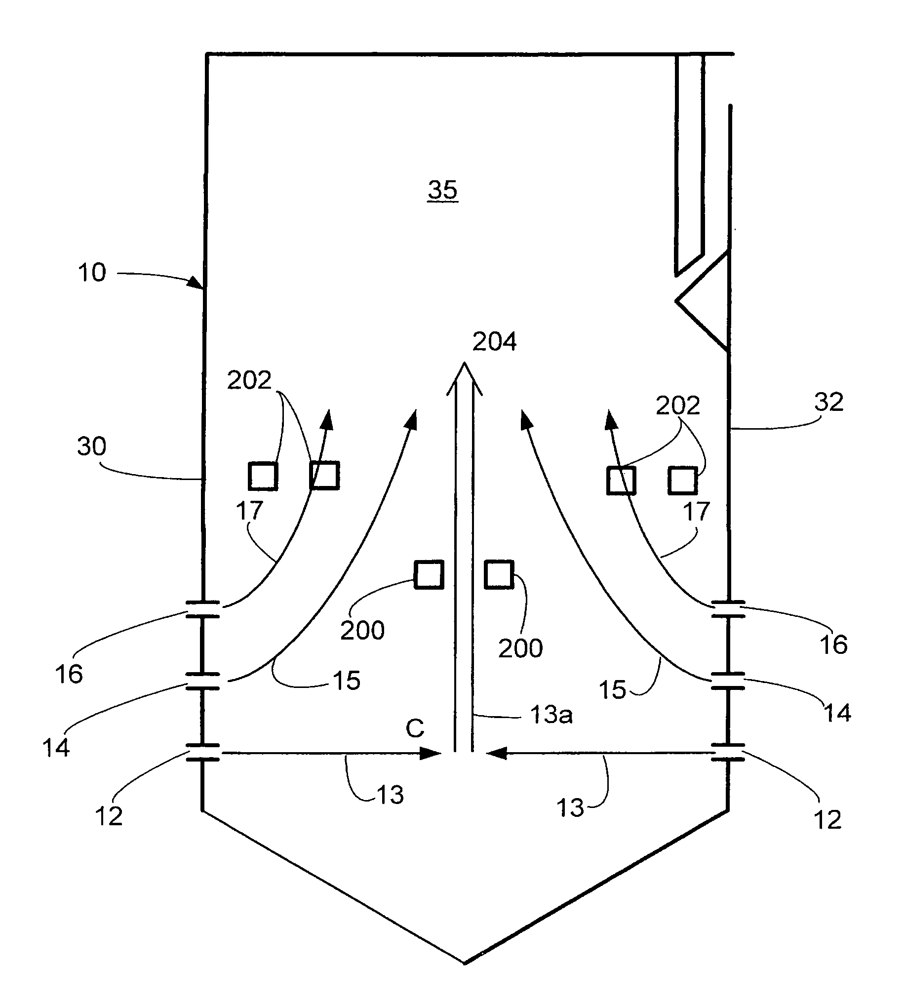
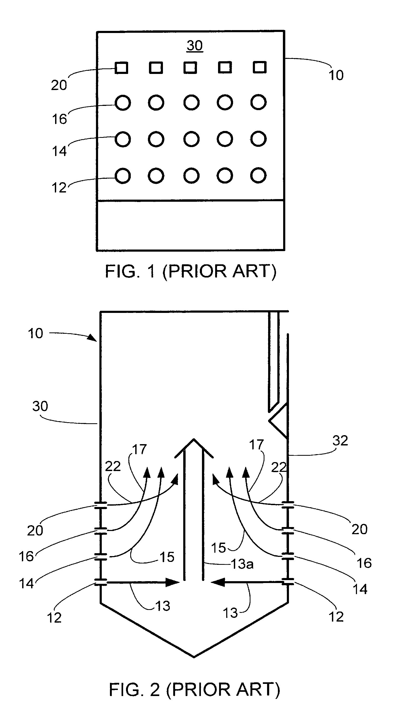
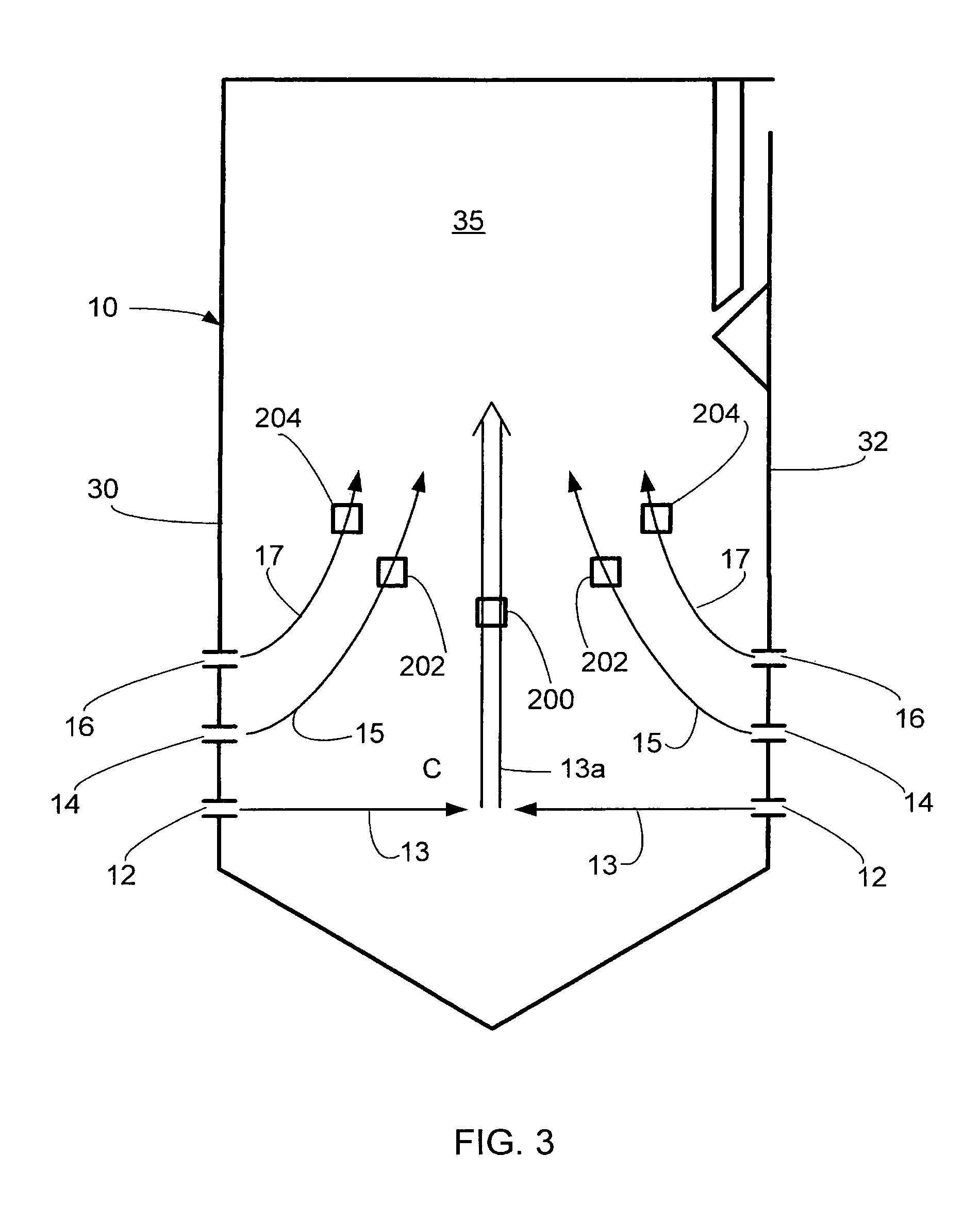
[0029]Referring now to the drawings, wherein which like reference numerals are used to refer to the same or functionally similar elements throughout the several drawings, FIGS. 3-6 each display a furnace enclosure 10 of an opposed-wall fired furnace including an OFA configuration of the invention. Like the enclosure 10 of FIGS. 1 and 2, in each of FIGS. 3-6, three burner levels 12, 14, 16 are located in the front and rear walls 30, 32, respectively. However, as will be appreciated by those skilled in the art, the present invention is applicable to single wall fired and opposed fired furnace enclosures 10 having fewer or a greater number of burner levels.

[0030]In FIG. 3, over fire air ports 200, 202, 204 are located in sidewalls 35, rather than the front or rear walls 30, 32. The OFA ports 200, 202, 204 are positioned so that the injected air will generally transversely intersect the burner flame paths 13a, 15, 17, respectively. That is, bottom OFA port 200 will inject over fire air ...


PUM


Abstract

An over fire air (OFA) port arrangement for a pulverized coal-fired boiler or furnace has at least one OFA port through each of the sidewalls for injecting OFA to increase residence time for each burner level. Plural OFA ports may be employed, staggered both vertically and horizontally to effectively deliver over fire air to the burner flames at the appropriate time and location to most efficiently reduce the formation of fuel NOx. OFA port configurations for both single-wall and opposed-wall fired furnaces and boilers are provided.

Description

FIELD AND BACKGROUND OF THE INVENTION[0001]The present invention relates generally to the field of industrial and utility furnaces and boilers and in particular to new and useful over fire air (OFA) port configurations for a pulverized coal-fired furnace or boiler which effectively reduce NOx production.[0002]NOx is an unintended byproduct from the combustion of fossil fuels, such as coal. Many industrial furnaces and boilers burn pulverized coal as a primary fuel. NOx emissions have been discovered to have a negative effect on the environment, and so they are now regulated substantially throughout the world.[0003]Most NOx in furnaces and boilers burning pulverized coal is formed during combustion from the fossil fuel. This portion of NOx formation is called fuel NOx. Fuel NOx is formed by oxidation of fuel-bound nitrogen during devolatilization and char burnout.[0004]An effective method of reducing NOx production which has been known for many years is to reduce oxygen availability ...

Claims


Application Information

Patent Timeline
Patent Type & Authority Patents(United States)
IPC IPC(8): F23D1/00F23L9/02
CPCF23L9/02
Inventor LARUE, ALBERT D.
Owner POLY MED
Why Eureka
Try Eureka