Modular plastic conveyor belt for spiral conversion

a conveyor belt and module technology, applied in the direction of conveyors, rollerways, transportation and packaging, etc., can solve the problems of inability to carry defined loads, and achieve the effects of increasing spanning strength, reducing the distance of protruding outwardly, and increasing depth

Inactive Publication Date: 2009-12-01
HABASIT AG
View PDF18 Cites 22 Cited by
  • Summary
  • Abstract
  • Description
  • Claims
  • Application Information

AI Technical Summary

Benefits of technology

[0007]In the current invention, a modular plastic conveyor belt, formed of successive rows of assembled injection molded modules connected by laterally-extending pins, has arched tops in each module row and increased depth in the laterally-extending spine of the belt. The belt structure enables the modular plastic belt to be retrofitted in a spiral system normally carrying a steel conveyor belt, although it can also replace a plastic spiral belt or be installed on new equipment. In one embodiment the arched-top module rows, having a greater module depth than normal, are accommodated on a small-diameter roller, by forming a generally cylindrical undercut at the bottom of each module row, reducing the distance of protrusion outwardly from the roller. For example, a 2½ inch pitch belt can be used on a roller designed for a 2 inch pitch belt (typical of some steel spiral systems) through the accommodation made by the arcuate undercut at the bottom of each module, and the belt can travel around a six-inch roller just as smoothly as will the smaller-pitched belt.
[0008]The arched-top configuration lends itself not only to transfer of articles as the conveyor passes over the sprocket for a roller, but also the provision of increased beam depth at the center of the module for increased spanning strength, with lower profiles at the extremities of the link ends. When the arched-top belt passes over sprockets or over a roller, changing the plane of travel, chordal action, i.e. radially outward protrusion of the belt knuckles as the belt passes over the sprocket, is substantially eliminated.
[0009]Thus, with a spiral conveyor belt made up of arched-top modules as in the invention, a plastic belt can be used in place of a steel belt on a spiral system that has only two rails spaced widely apart. The arched (curved) tops increase the beam strength at the center of each module row to the point that a given load can be carried on the spiral system, spanning between two support rails, whereas a similar plastic belt with a flat top surface, with the center spine height no larger than the link ends, would fail or would deeply sag under that given load, thus would be incapable of carrying the defined load. The high center spine provided by the arched configuration gives the belt such greatly increased beam strength that it can substitute for a steel belt for which the spiral system was designed, in nearly all situations. The belt and the belt conversion of the invention enable a plastic belt to travel through the same relatively tight curve radius around the spiral tower, while still being able to carry a relatively heavy load of conveyed goods while spanning between the spaced apart rail supports, and while still providing a large open area for airflow through the belt via the minimum supporting rail area. Cost and inconvenience of converting a steel spiral system to plastic are greatly reduced, with no need to re-engineer, add further support rails, etc.
[0010]In spiral conveyors handling food products, about 80% of the spirals currently installed are used for panned or packaged product, which are efficiently conveyed on the arched tops, and the arched tops provide for minimum contact with the belt for increased cooling due to more air flow around the product. The balance of spiral conveyors directly contact the food products; the belt of the invention works well with foods of large enough size.
[0011]For accommodating a tight turn radius for curves in one direction, the module rows in the belt of the invention preferably have a reduced thickness in the spine on the inner side of the curve, i.e. less thickness from front to back of the spine, allowing a greater degree of collapse at the inner side. The spine at the outer side preferably is not of reduced thickness. Another feature is that the link ends, which are alternatingly interdigited from one module row to the next, preferably have rod-supporting lateral projections that circumscribe only part of the rod and which overlap in position between link ends of one module row and interdigited link ends of another module row. These provide a greater width of engagement against the rod for placing the pressure of the belt tension against the rod over a wider area, thus reducing bending moment on the rod and increasing the tension that can be withstood by the rod without deflection or failure.
[0013]It is thus among the objects of this invention to enable an efficient, convenient and economical conversion of a steel spiral conveyor system to a plastic modular conveyor belt, while also providing for increased air flow, smooth transfer of items onto and off the plastic belt, and efficient cleaning by scraping the belt while it forms a cylindrical surface over a roller. These and other objects, advantages and features of the invention will be apparent from the following description of a preferred embodiment, considered along with the accompanying drawings.

Problems solved by technology

The arched (curved) tops increase the beam strength at the center of each module row to the point that a given load can be carried on the spiral system, spanning between two support rails, whereas a similar plastic belt with a flat top surface, with the center spine height no larger than the link ends, would fail or would deeply sag under that given load, thus would be incapable of carrying the defined load.

Method used


Image

  • Modular plastic conveyor belt for spiral conversion
  • Modular plastic conveyor belt for spiral conversion
  • Modular plastic conveyor belt for spiral conversion

Examples


Embodiment Construction

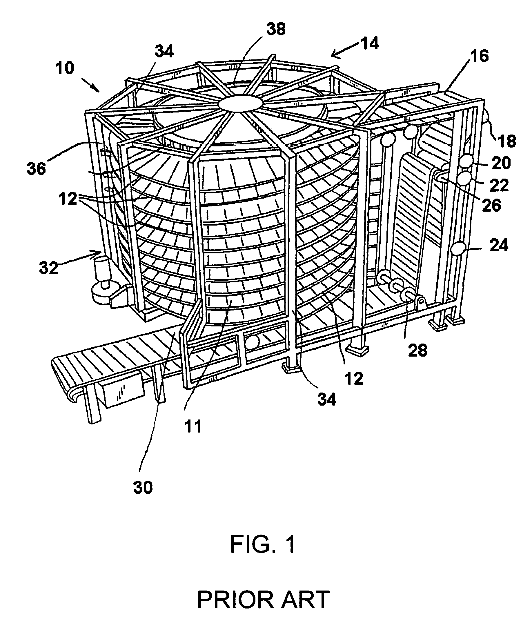
[0023]In the drawings, the perspective view of FIG. 1 schematically illustrates a spiral conveyor system 10 in which a conveyor belt 11 travels in a helical path through a series of tiers 12 in a driving tower 14. The conveyor 12 normally rises through the helix defined by the driving tower, exits off the upper end of the tower at 16 and passes over a series of rollers 18, 20, 22, 24, 26, 28, etc. as schematically shown in the drawing, ultimately to be fed back into the bottom of the helical path of the conveyor tower at 30.

[0024]As is well known, a spiral conveyor system normally has a support frame 32 which includes a series of columns 34 around the circumference of the conveyor belt, and these have inwardly-extending cantilevered beams or bars 36, some of which are indicated in the schematic view of FIG. 1. These, in the typical steel spiral conveyor belt system, support two or sometimes three tracks that follow the helical path to support the width of the belt 11. These tracks (...


PUM


Abstract

A modular plastic conveyor belt, formed of successive rows of assembled injection molded modules connected by laterally-extending pins, has arched tops in each module row and increased depth in the laterally-extending spine of the belt. The belt structure enables the modular plastic belt to be retrofitted in a spiral system normally carrying a steel conveyor belt. In one embodiment the arched-top module rows, having a greater depth than normal, are accommodated on a small-diameter roller, by forming a generally cylindrical undercut at the bottom of each module row, reducing the distance of protrusion outwardly from the roller. The arched-top configuration lends itself not only to transfer of articles as the conveyor passes over the sprocket for a roller, but also the provision of increased beam depth at the center of the module, with lower profiles at the extremities of the link ends.

Description

BACKGROUND OF THE INVENTION[0001]This invention encompasses a conversion for spiral conveyor belt systems, by which a modular plastic conveyor belt is fitted onto a spiral tower designed for carrying a steel spiral conveyor.[0002]Spiral conveyors have experienced increasing use in past decades particularly in the food industry, and they are also finding more and more uses in other manufacturing operations. They enable dwell time on a spiral tower in what is technically a helical path, the conveyor belt being driven up the curving incline in a low tension arrangement, primarily by engagement with a rotating driving tower at the center. Spiral conveyors initially, and for many years, comprised all steel belts, usually stainless steel for the food industry.[0003]However, with the advent of plastic modular conveyor belts, capable of assembly in any length and virtually any width, some spiral conveyor belt systems were fabricated from modular plastic conveyor belts. Plastic materials hav...

Claims


Application Information

Patent Timeline
Patent Type & Authority Patents(United States)
IPC IPC(8): B65G21/18
CPCB65G17/40B65G17/086
Inventor DELAIR, JEFFREY EARLBICKEL, JR., WILLIAM J.
Owner HABASIT AG
Why Eureka
Try Eureka