Piezoelectric resonator with optimised motional capacitances

a technology of motional capacitance and resonator, which is applied in piezoelectric/electrostrictive/magnetostrictive devices, piezoelectric/electrostriction/magnetostriction machines, impedence networks, etc. it can solve the problems of increasing the equivalent resistance, reducing the power consumption, and reducing the equivalent resistance, so as to increase the security, reduce the space, and be easily adjusted

Active Publication Date: 2009-12-01
ETA SA MFG HORLOGERE SUISSE
View PDF11 Cites 39 Cited by
  • Summary
  • Abstract
  • Description
  • Claims
  • Application Information

AI Technical Summary

Benefits of technology

[0010]It will be understood that a piezoelectric tuning fork resonator of the type described in the preamble of claim 1 has in particular a first motional capacitance for a first frequency, called the fundamental frequency, and a second motional capacitance for a second frequency, called the partial frequency. It will also be understood that the features forming the subject of this invention advantageously allow said first motional capacitance of the resonator to be increased for the fundamental frequency, and said second motional capacitance to be decreased for the partial frequency. They also ensure better distribution of the mechanical stress along the vibrating arms and increase shock resistance.
[0021]The grooves may be either of rectangular shape, to reduce the space between the electrodes and thus further increase the first motional capacitance, or of a tapered shape fitting the shape of the arms to prevent any short circuits between the electrodes.

Problems solved by technology

In equal dimensions, this increase in the coupling causes a decrease in the equivalent resistance for a given resonator quality factor and consequently a decrease in the power consumption thereof.
However, below a certain dimension, the decrease in volume of the elastically active piezoelectric material is associated with a decrease in quality factor, which causes an undesirable increase in the equivalent resistance.

Method used


Image

  • Piezoelectric resonator with optimised motional capacitances
  • Piezoelectric resonator with optimised motional capacitances
  • Piezoelectric resonator with optimised motional capacitances

Examples


Embodiment Construction

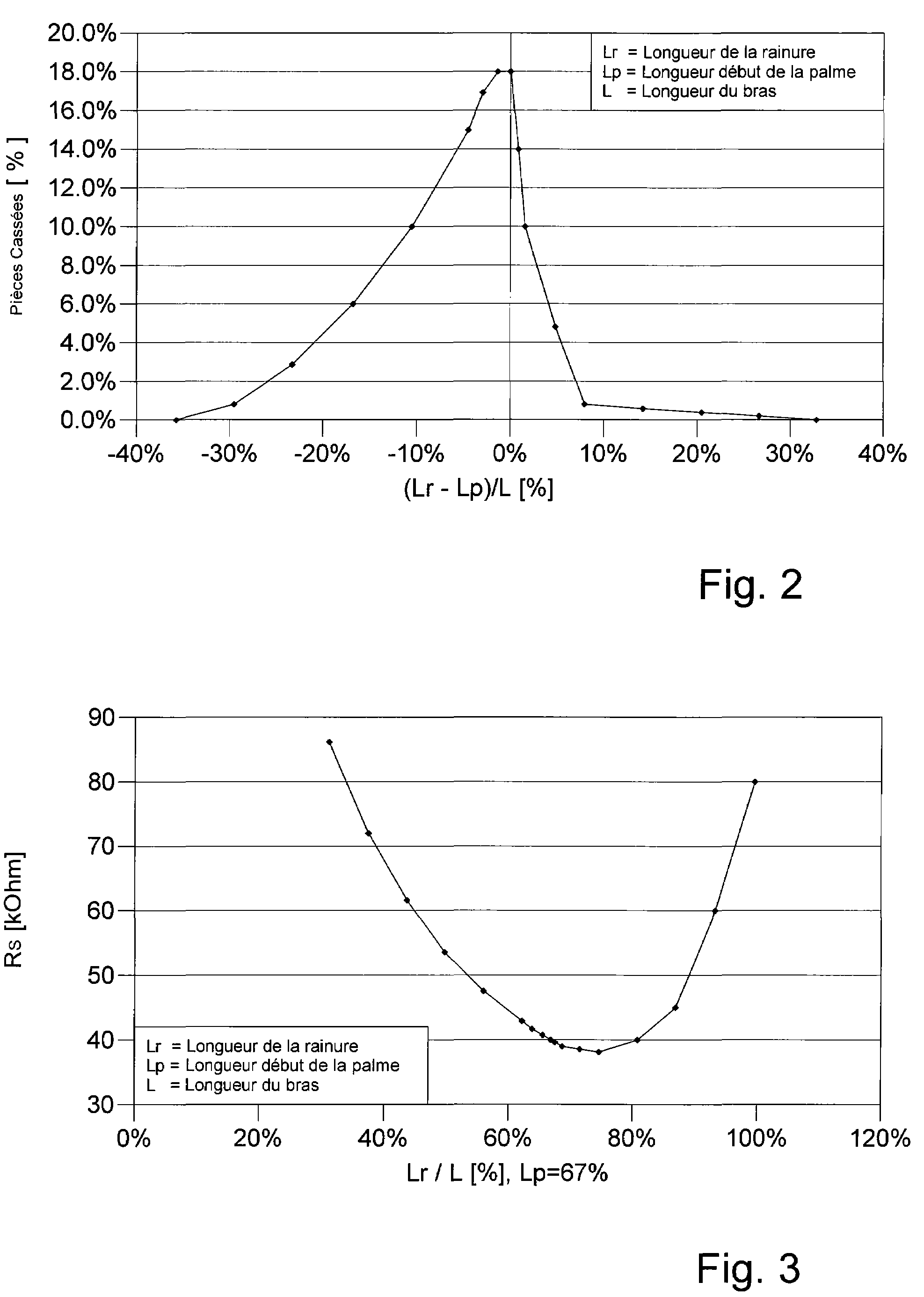
[0027]The invention will be described below with reference to a non-limiting example given with reference to FIGS. 1 to 3.

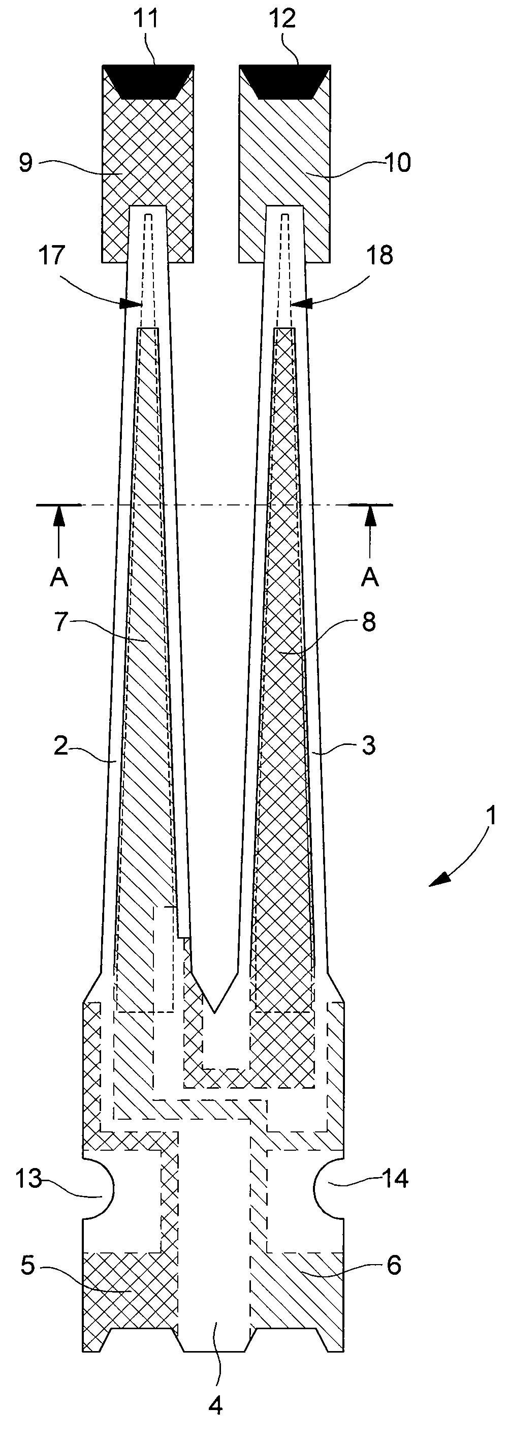
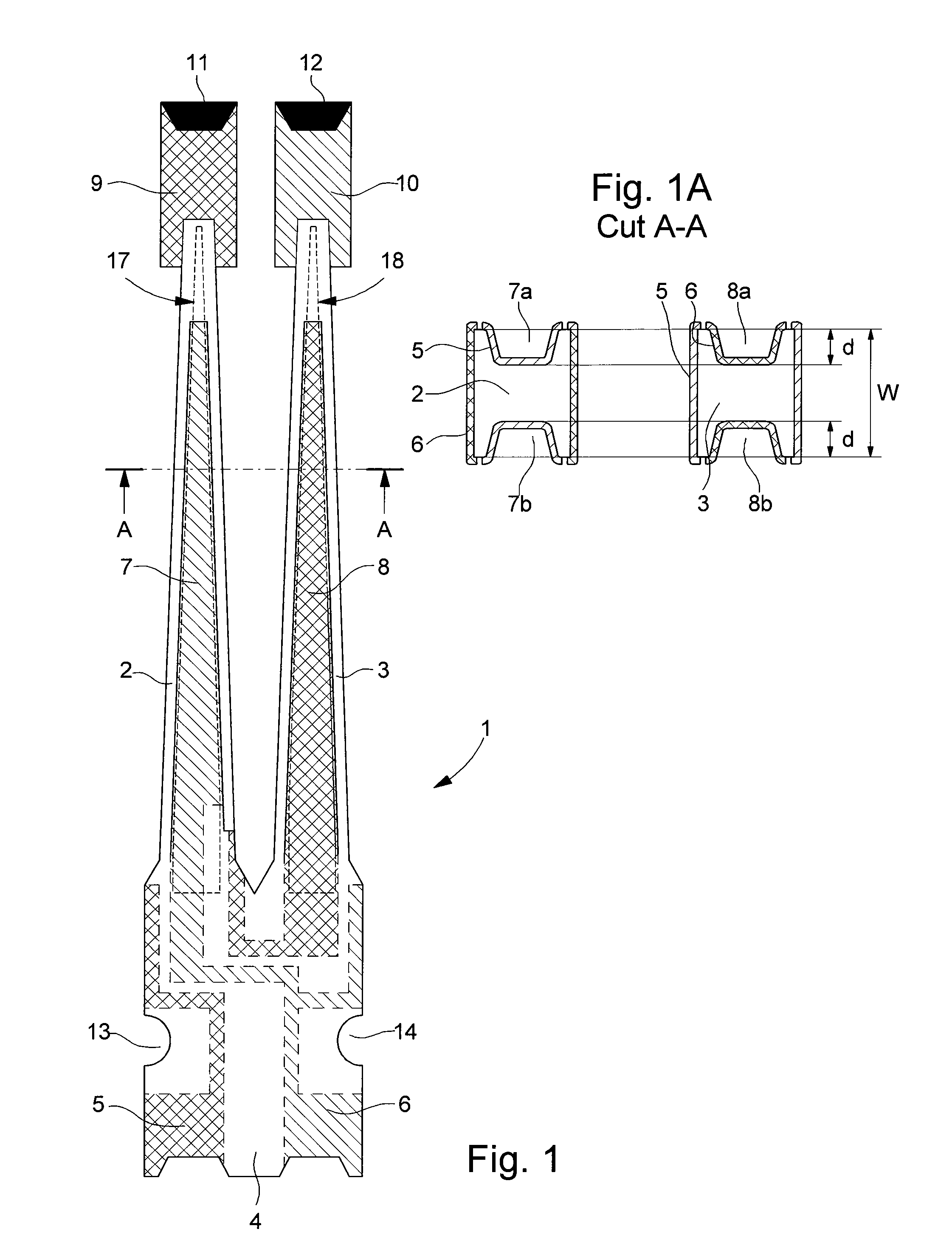
[0028]In the particular embodiment which is shown in FIG. 1, the resonator, designated by the reference 1, includes a tuning fork part including two vibrating arms 2 and 3 joined by a base 4, the assembly being made in a single piece in a piezoelectric material, such as quartz. Base 4 and arms 2 and 3 carry metallised portions, i.e. conductive depositions, which form a set of electrodes 5 and 6, which enable the arms to be subjected to electric fields in order to make them vibrate at a desired frequency, called the fundamental frequency. The metallised portions formed on the arms form the central electrodes on the main opposite surfaces and lateral electrodes along the sides of each arm. Grooves 7 and 8 are also formed in at least one of the front or back faces of each vibrating arm. The Figure shows that these grooves 7 and 8 start inside base 4 and extend along...


PUM


Abstract

The tuning fork resonator (1) includes a base (4) from which first and second parallel vibrating arms (2, 3) extend, carrying a set of excitation electrodes (5, 6) for vibrating the arms at a fundamental frequency. Grooves (7, 8) are formed on at least one of the top or bottom surfaces of each of said arms. The vibrating arms have a generally tapered shape, and are extended by an enlarged flipper shaped portion (9, 10) which forms the free end of each arm. The groove (7, 8) is extended in the direction of the free end of an arm to beyond the start of the flipper (9, 10) so as to increase said first motional capacitance of the resonator for the fundamental frequency, to decrease said second motional capacitance of the resonator for the partial frequency and to ensure better distribution of mechanical stress along the vibrating arms and to increase shock resistance.

Description

[0001]This application claims priority from European Patent Application No. 07014189.0, filed Jul. 19, 2007, the entire disclosure of which is incorporated herein by reference.FIELD OF THE INVENTION[0002]The present invention concerns piezoelectric resonators and more specifically resonators of small dimensions which are most often used for making frequency generators, in particular for portable electronic equipment used in various fields, such as horology, information technology, telecommunication and the field of medicine.BACKGROUND OF THE INVENTION[0003]Resonators of this type with small dimensions have already been disclosed in the prior art document U.S. Pat. No. 4,384,232, which is incorporated herein by reference. That document discloses a tuning fork resonator formed of a base and two vibrating arms extending from the base. Each arm carries metallised portions that form central electrodes on the main opposite surfaces and lateral electrodes along the sides of each arm. The c...

Claims


Application Information

Patent Timeline
Patent Type & Authority Patents(United States)
IPC IPC(8): H01L41/08
CPCH03H9/215
Inventor DALLA PIAZZA, SILVIOSTUDER, BRUNOSTAUB, FELIX
Owner ETA SA MFG HORLOGERE SUISSE
Why Eureka
Try Eureka