
Laser amplifier and method of making the same

a laser amplifier and amplifier technology, applied in the field of lasers, can solve the problems of reducing so as to improve waste heat management, improve the efficiency of laser amplifiers, and improve the effect of compact packag

Active Publication Date: 2009-12-01
STC UNM
View PDF12 Cites 1 Cited by
  • Summary
  • Abstract
  • Description
  • Claims
  • Application Information

AI Technical Summary

Benefits of technology

The present invention is a laser amplifier that has high power performance and improved waste heat management in a compact package. It includes a gain medium layer, a coupling layer, and an evanescent layer. The evanescent layer has a lower index of refraction than the coupling layer and the gain medium layer, which allows light to enter the evanescent layer at a certain angle and be transmitted into the gain medium through total internal reflection. The amplified light then exits the gain medium through the evanescent layer and into a larger laser cavity. The laser amplifier has a smaller size and higher power output compared to traditional amplifiers. It can also be combined with external mirrors for light reflection.

Problems solved by technology

However, in spite of recent improvements in edge emitting diode laser design, the spatial beam quality of these lasers is relatively poor thereby degrading the source brightness.
In spite of the successes enjoyed by OP-VECSEL systems, they have a number of disadvantages including the incorporation of relatively thick, expensive and cumbersome dielectric stack mirrors.
Moreover, these mirrors will act both as a heating source as well as introducing thermal impedance between the active medium and the heat sink, which in turn can limit the power output of the system as a whole.

Method used


Image

  • Laser amplifier and method of making the same
  • Laser amplifier and method of making the same
  • Laser amplifier and method of making the same

Examples


Embodiment Construction

[0021]The following description of the preferred embodiments is provided to enable any person skilled in the art to make or use the present invention. Various modifications to these embodiments will be readily apparent to those skilled in the art, and the generic principles defined herein may be applied to other embodiments without departing from the spirit or scope of the invention as set forth in the appended claims.

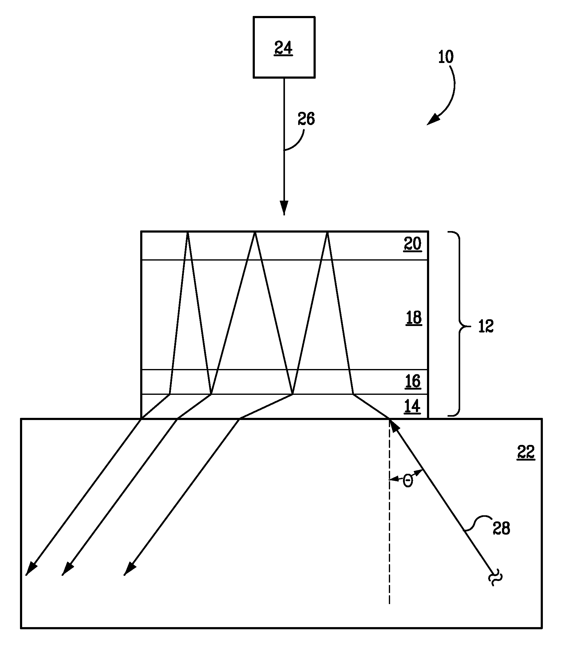
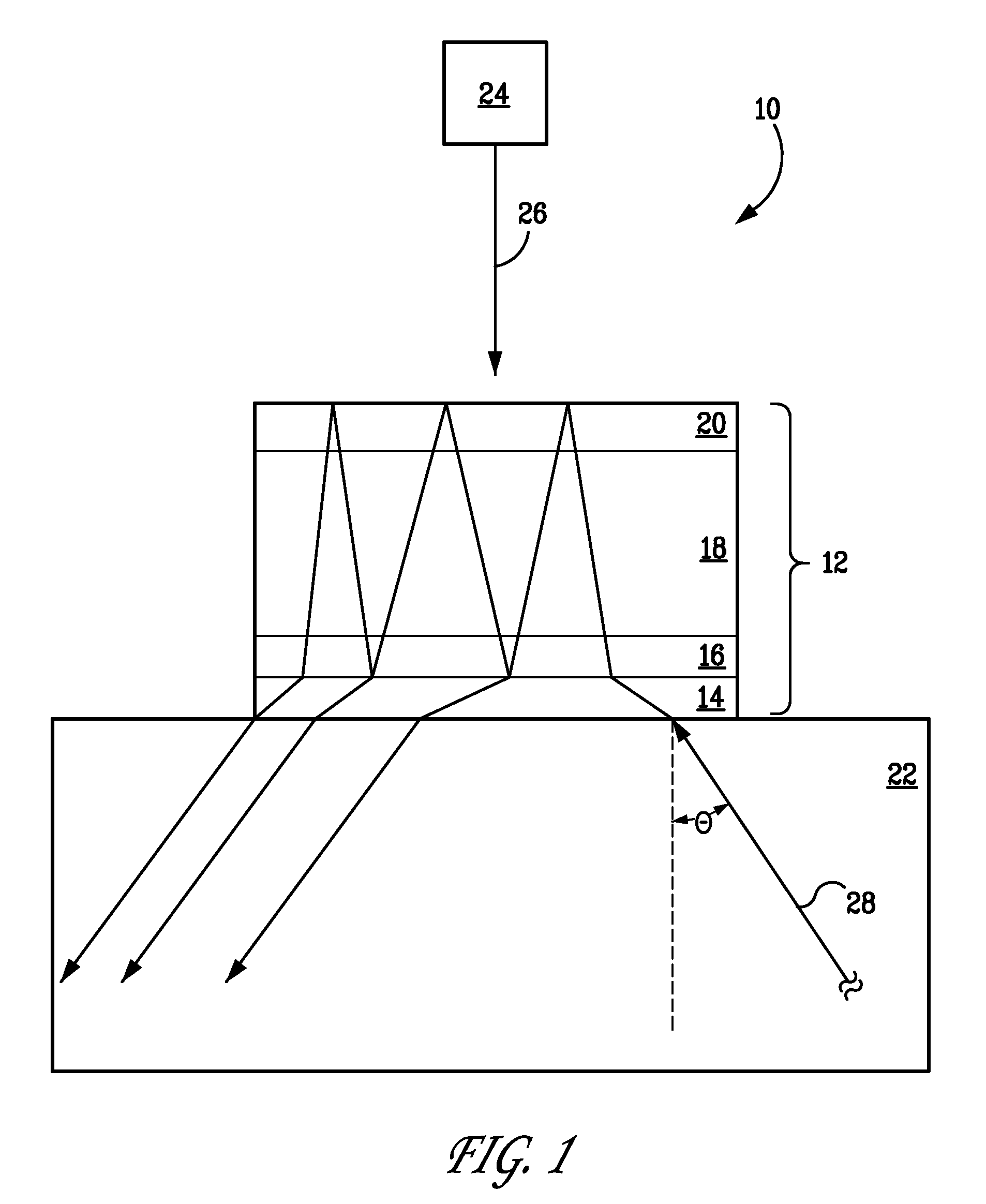
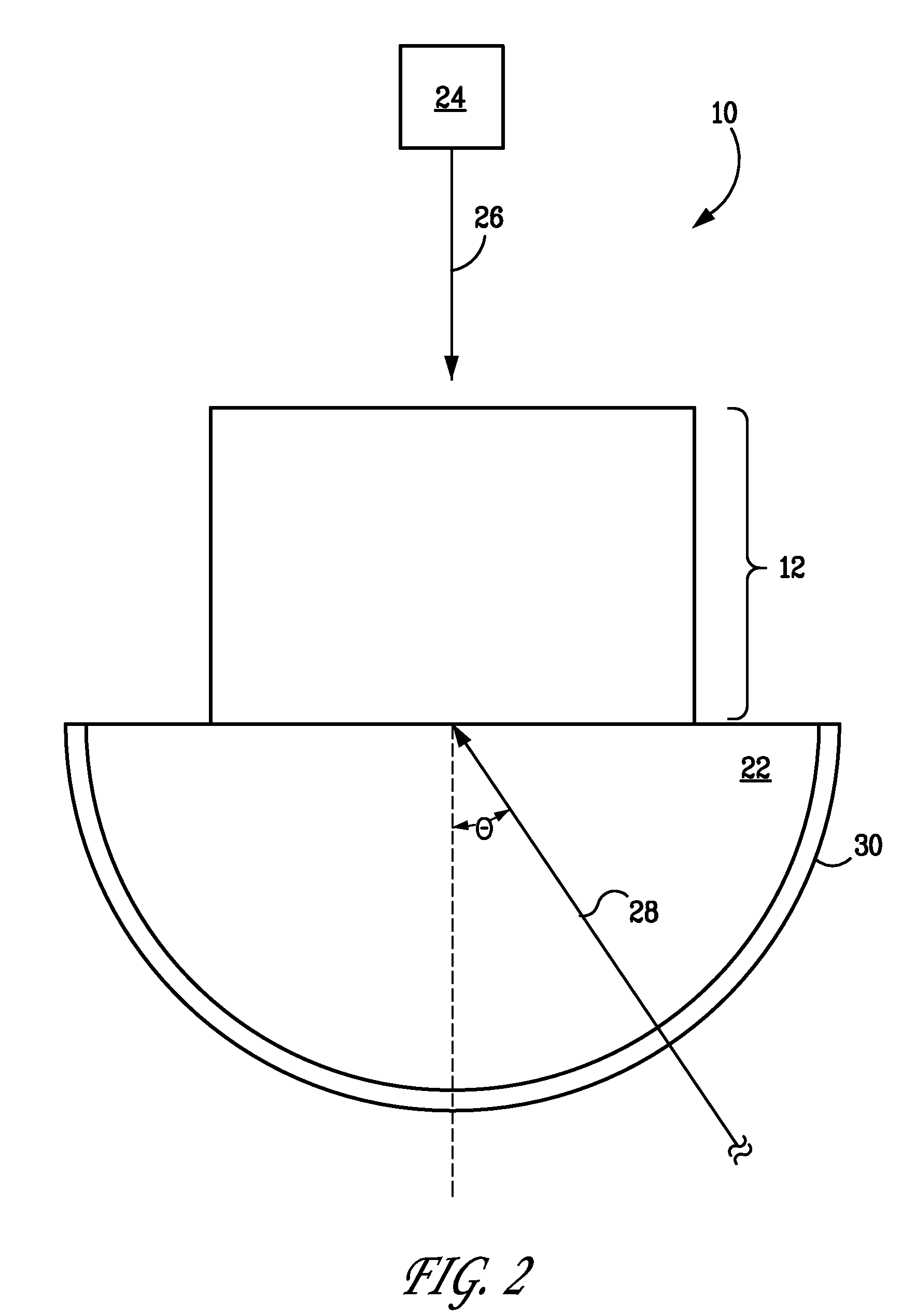
[0022]As shown in FIG. 1, a preferred embodiment of the present invention includes a laser amplifier 10 having a gain medium layer 18 having a first index of refraction, and a coupling layer 22 optically coupled to the gain medium. In the laser amplifier 10 of the preferred embodiment, the coupling layer 22 has a second index of refraction less than the first index of refraction. The laser amplifier 10 of the preferred embodiment also includes an evanescent layer 14 disposed between the gain medium and the coupling layer 22. The evanescent layer 14 can have a third ind...


PUM


Abstract

The present invention includes a laser amplifier and a method of making the same. The laser amplifier of the present invention includes a gain medium layer having a first index of refraction, and a coupling layer optically coupled to the gain medium. In the various embodiments described herein, the coupling layer can have a second index of refraction less than the first index of refraction. The laser amplifier described herein can also include an evanescent layer disposed between the gain medium and the coupling layer. The evanescent layer can have a third index of refraction less than the second index of refraction. The laser amplifier provides high power, efficient laser resonance through frustrated total internal reflection and total internal reflection while simultaneously providing for the minimization of waste heat in the gain medium layer.

Description

CLAIM OF PRIORITY UNDER 35 U.S.C. §119[0001]The present Application for Patent claims priority to provisional application Ser. No. 60 / 840,276, entitled “Evanescent-Wave-Subcavity Amplifiers and Lasers”, filed on Aug. 25, 2006, and to provisional application Ser. No. 60 / 921,754, entitled “Evanescent-Wave-Subcavity Active Mirror and its Method of Manufacture”, Filed on Apr. 4, 2007, both of which are assigned to the assignee hereof and hereby expressly incorporated by reference herein.BACKGROUND[0002]1. Field of the Present Invention[0003]The present invention relates generally to the field of lasers, and more specifically to the field of high power laser amplifiers and methods of making the same.[0004]2. History of the Related Art[0005]With the invention of solid-state lasers, the design and uses of lasers in consumer applications has risen dramatically. Small and powerful diode lasers are nearly ubiquitous in numerous kinds of consumer electronics, and they are finding still more ap...

Claims


Application Information

Patent Timeline
Patent Type & Authority Patents(United States)
IPC IPC(8): H01S3/08H01S3/00H01S5/00
CPCH01S3/0612H01S3/2325H01S3/08095H01S3/0405H01S3/042H01S3/0621H01S3/0813H01S3/094H01S3/08059
Inventor SHEIK-BAHAE, MANSOOR
Owner STC UNM
Learn More