In-line distortion cancellation circuits for linearization of electronic and optical signals with phase and frequency adjustment

a technology of phase and frequency adjustment and cancellation circuit, which is applied in the direction of pulse manipulation, pulse technique, amplifier modification to reduce non-linear distortion, etc., can solve the problems of high rf loss in the transmission path, low insertion loss, and insufficient flexibility to create different frequency and phase characteristics. , to achieve the effect of low insertion loss, high amount of distortion, and good return loss

Active Publication Date: 2009-12-15
EMCORE INC
View PDF111 Cites 11 Cited by
  • Summary
  • Abstract
  • Description
  • Claims
  • Application Information

AI Technical Summary

Benefits of technology

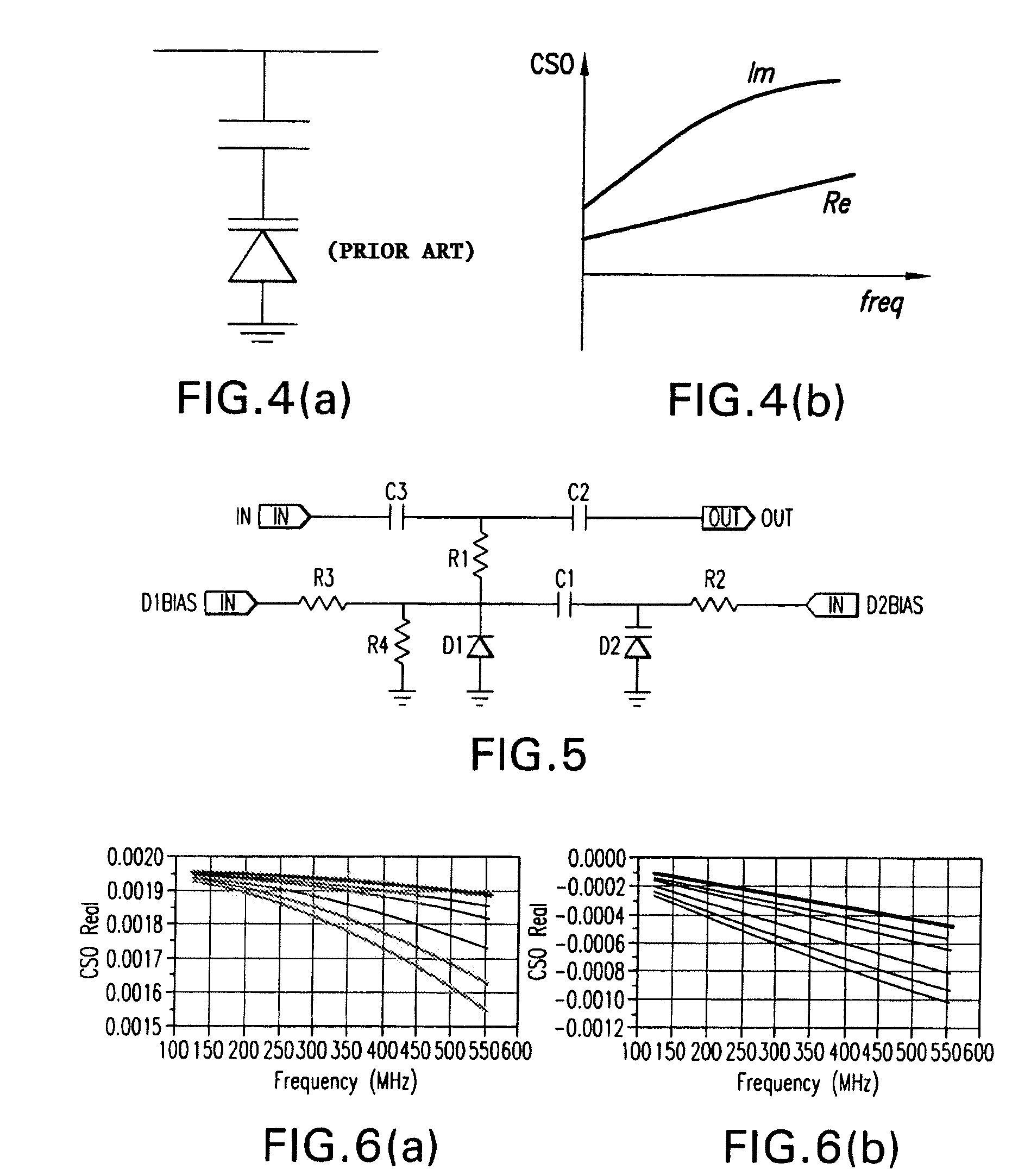
[0008]It is an object of the present invention to provide circuits that allow simultaneous tuning of the phase and frequency response of the second order distortion.
[0009]It is also another aspect of the present invention to provide a circuit that generates high amounts of distortion with low insertion loss and good return loss.

Problems solved by technology

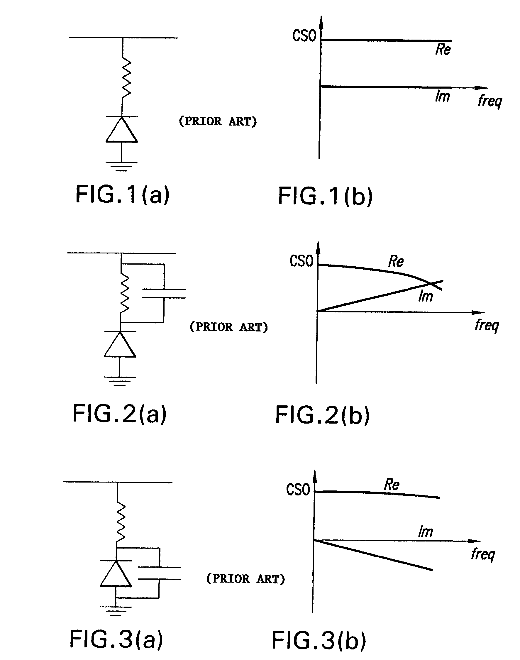
However, while pre- and post-distortion circuits described in the prior art are able to achieve sufficient degree of pre-distortion for some applications, they do not provide enough flexibility to create different frequency and phase characteristics.
For example, RF amplifiers operated with low supply voltage for lower power dissipation require a large amount of distortion
Some distortion circuits disclosed in U.S. Pat. No. 5,798,854 can introduce high RF loss in the transmission path and create undesired reflections when large amounts of distortion need to be generated.
There are requirements that will enable large distortion with low loss and low reflection that are not satisfied by the prior art design.
Moreover, some distortion circuits, such as those disclosed in U.S. Pat. No. 5,798,854 that are designed to correct second order distortion also produce undesired third order distortion, and such designs do not allow tuning of both second and third order distortion simultaneously.

Method used


Image

  • In-line distortion cancellation circuits for linearization of electronic and optical signals with phase and frequency adjustment
  • In-line distortion cancellation circuits for linearization of electronic and optical signals with phase and frequency adjustment
  • In-line distortion cancellation circuits for linearization of electronic and optical signals with phase and frequency adjustment

Examples


Embodiment Construction

[0031]The present invention is directed to a distortion correaction circuit that extends the notion of distortion correaction as set forth in U.S. Pat. No. 5,798,854. The above noted patent discloses an in-line predistortion circuit for reducing distortion in the transmission of analog signals. The distortion so generated by such a circuit, or predistortion, is fixed for a given circuit to be substantially equal in magnitude and opposite in sign to the second or higher order intermodulation product distortion inherent in a nonlinear modulation device such as a laser diode to which the signal is applied. The real component of the predistortion signal is produced by a first device such as an amplifier, and is selected in amplitude to match the amplitude of the distortion by the nonlinear device. The imaginary component of the predistortion signal is selected through introduction of a distortion signal out phase with the real component of the predistortion signal on the in-line electri...


PUM


Abstract

A distortion circuit is provided for correcting the distortion from a nonlinear circuit element by generating a frequency dependent signal having a sign opposite to the distortion signal produced by the nonlinear circuit and substantially the same magnitude. The distortion circuit includes an input signal and a first nonlinear device coupled to the input signal for generating a first signal and where the first nonlinear device has a first bias level. Also included is a second nonlinear device different from same first nonlinear device and coupled to the first nonlinear device for modifying the first signal to produce an output second signal, the second nonlinear device having a second bias level. A bias control means is provided for adjusting the first and said second bias levels so that the magnitude, phase and frequency of the output second signal can be adjusted.

Description

REFERENCE TO RELATED APPLICATIONS[0001]This application is related to U.S. patent application Ser. No. 11 / 262,077 filed Oct. 27, 2005 and U.S. application Ser. No. 11 / 148,022 filed Jun. 9, 2005.BACKGROUND OF THE INVENTION[0002]1. Field of the Invention[0003]The invention relates to optical transmitters and receivers, and in particular to electronic circuits that generates a nonlinear signal with adjustable phase and frequency dependence that can be used to cancel the distortion of electronic or electro-optical devices, such as semiconductor lasers or photodiodes, when connected either at the input or at the output of the device that needs to be linearized.[0004]2. Description of the Related Art[0005]Analog electro-optical devices such as lasers and photodiodes used in CATV and FTTH systems require a high degree of linearity. Pre-distortion and post-distortion circuits are commonly employed to correct the nonlinear behavior of opto-electronic and electronic devices by adding a nonlin...

Claims


Application Information

Patent Timeline
Patent Type & Authority Patents(United States)
IPC IPC(8): H04B10/18H04B10/00H03F1/34H03F3/08H03F5/00H04B10/43
CPCH03F1/32H03F1/3241H04B10/58H03F3/08H03F1/3276H03F2200/63H04B10/2507H04B10/40
Inventor PERAL, EVA
Owner EMCORE INC
Why Eureka
Try Eureka