Method and apparatus for location determination of people or objects

a technology for location determination and people or objects, applied in direction finders, direction finders using radio waves, instruments, etc., can solve the problems of reducing tracking accuracy, multiple story buildings posing additional obstacles for tracking, and difficult or even impossible to cover large steel and concrete buildings, etc., to facilitate the portability of transmitter nodes, reliable and accurate location determination, the effect of enhancing the angular geometry of transmission

Inactive Publication Date: 2009-12-22
THOMAS ALAN +1
View PDF45 Cites 51 Cited by
  • Summary
  • Abstract
  • Description
  • Claims
  • Application Information

AI Technical Summary

Benefits of technology

[0023]The invention also provides reliable, accurate location determination when the transmissions from each of the transmitter nodes are out of phase (un-synchronized). In addition, the invention facilitates the portability of transmitter nodes, which may enhance the angular geometry of the transmissions relative to the receiving device, resulting in enhanced 3-D location determination in virtually any rural, suburban, or urban region.
[0024]The invention provides the capability to position transmitter nodes virtually anywhere, thus enhancing angular geometry and location accuracy.

Problems solved by technology

Unfortunately, large steel and concrete buildings, subways and large malls may be difficult or even impossible to cover using traditional wide area location technologies, because low signal-to-noise ratio and signal multipath effects in these environments often decrease tracking accuracy or even prevent signal acquisition.
Multiple story buildings pose additional obstacles for tracking, as they require three-dimensional positioning.
Even if the longitude and latitude of an individual in a fifty-story building were known with great accuracy, that knowledge would be insufficient because the emergency team may have to search every floor.
This procedure takes several minutes in weak signal environments.
The accuracy of this approach is suspect, due to the fact the RF transmission is performed at (relatively) low power and is not reliable at great distances or indoor environments.
A drawback is that the solution may not provide sufficient geographic dispersion of the broadcast stations to obtain reliably accurate fixes.
Further, this solution will not provide reliably accurate 3-d fixes because the probable location of the transmission stations does not provide the necessary angular geometry to accurately measure elevation.

Method used


Image

  • Method and apparatus for location determination of people or objects
  • Method and apparatus for location determination of people or objects
  • Method and apparatus for location determination of people or objects

Examples


Embodiment Construction

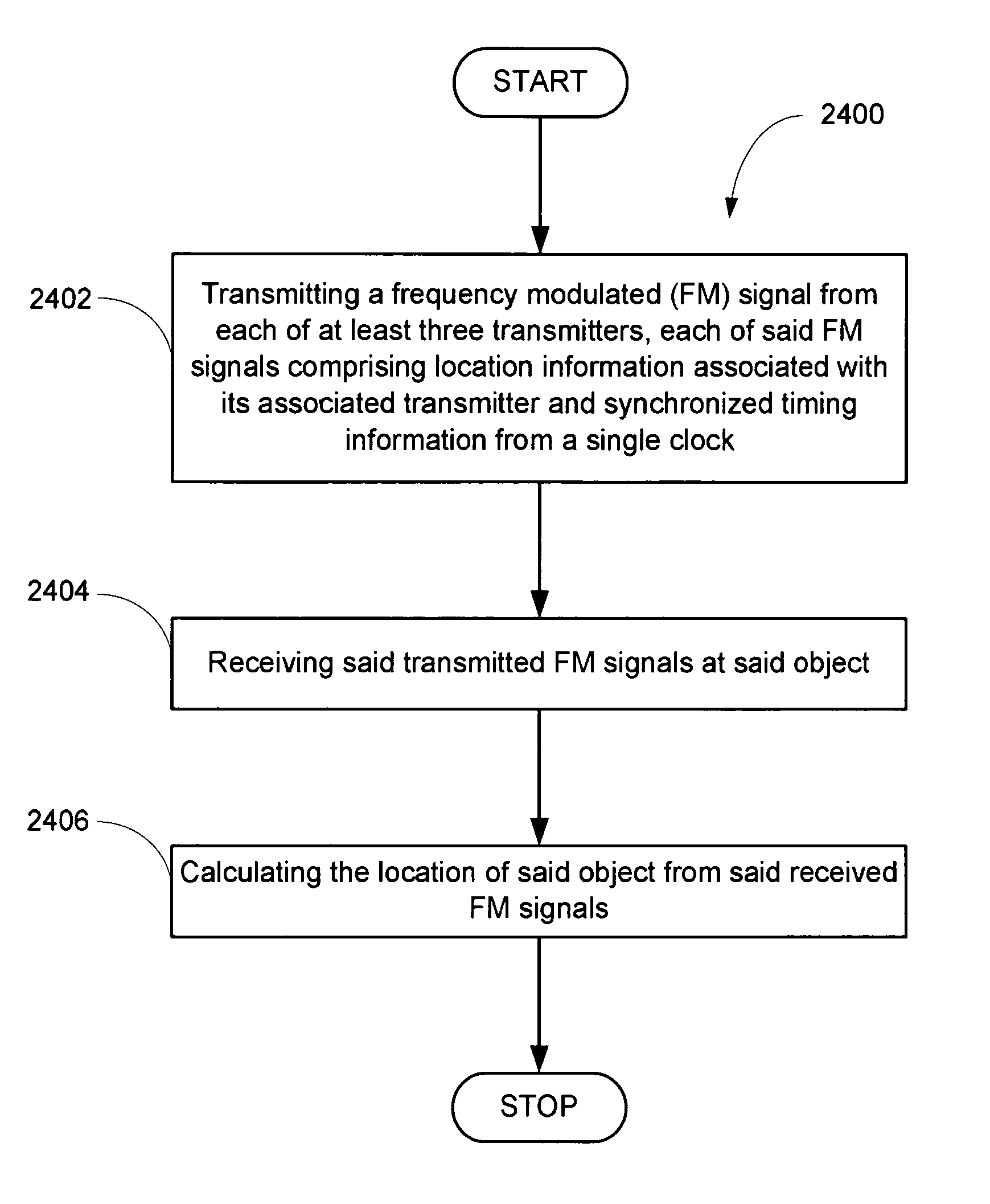
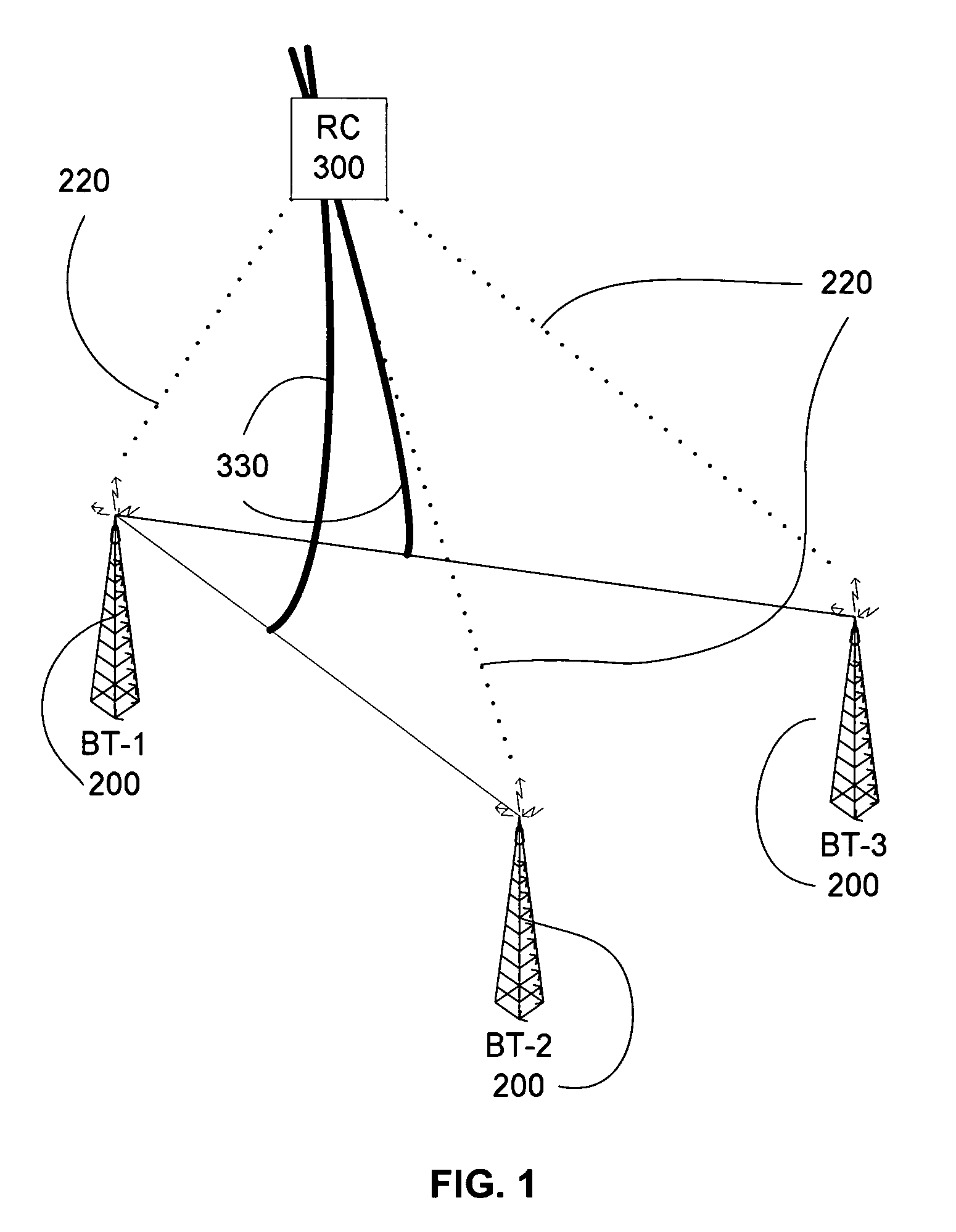
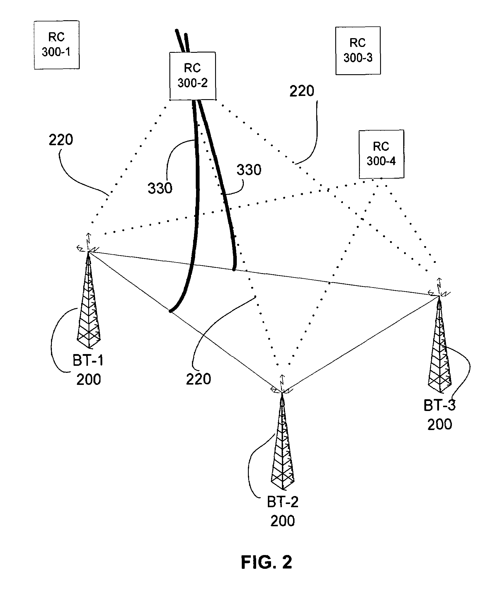
[0051]This present invention may utilize three or more geographically-dispersed transmitter nodes (hereinafter called a “BT node”). Each BT node may consist of an FM transmitter, a high-precision timing source (optional), high-precision location determination device (optional), FM receiver (optional), and computer processor, according to embodiments of the present invention. See FIG. 3 for a block diagram of an embodiment of a BT node.

[0052]The present invention may also include one or more Receiver nodes (hereinafter called “RC” node). Each RC node monitors 3 or more BT channels—the RC node may choose channels according to any specific criteria. Two possible examples of BT selection are: (1) monitoring those channels that exhibit the “strongest” signal, or (2) acquiring signals based upon the locations of their source BT nodes.

[0053]Each RC node (see FIG. 4 for a block diagram of an embodiment of an RC node) calculates the Time Difference of Arrival (TDOA) between each pair of BT s...


PUM


Abstract

A system and method for determining the position of people and/or objects, whether mobile or stationary, is presented herein. The system uses fixed and/or portable FM transmitters to transmit synchronized signals. These signals are acquired by a Receiver device which uses the signal timing to perform Time Difference of Arrival calculations to determine the Receiver's location. Then, using some arbitrary communications method, such as wireless communications, the Receiver device can forward its location to some arbitrary type of application system.

Description

CROSS-REFERENCE TO RELATED APPLICATIONS[0001]This nonprovisional patent application claims benefit and priority under 35 U.S.C. § 119(e) of the filing of U.S. Provisional Patent Application Ser. No. 60 / 680,865, filed May 16, 2005, titled: “Method and apparatus for tracking and reporting the location of people or objects in a local area”, U.S. Provisional Patent Application Ser. No. 60 / 673,025, filed, Apr. 21, 2005, titled: “Method and apparatus for relative location determination of people or objects in a local area” and U.S. Provisional Patent Application Ser. No. 60 / 682,666, filed, May 20, 2005, titled: “Method and apparatus for absolute location determination of people or objects in a defined area” all by the present inventors.BACKGROUND OF THE INVENTION[0002]1. Field of the Invention[0003]This invention relates to location determination of one or more wireless devices.[0004]2. Prior Art[0005]Location determination technology—the ability to identify the location of electronic dev...

Claims


Application Information

Patent Timeline
Patent Type & Authority Patents(United States)
IPC IPC(8): G01S1/02G01S3/02
CPCG01S5/10
Inventor THOMAS, ALANJEWETT, DAVID THOMAS
Owner THOMAS ALAN
Why Eureka
Try Eureka