
Electrode plate for electrochemical measurements

Active Publication Date: 2009-12-29
PANASONIC CORP
View PDF22 Cites 7 Cited by
  • Summary
  • Abstract
  • Description
  • Claims
  • Application Information

AI Technical Summary

Benefits of technology

[0077]According to the present invention, an electrode plate for electrochemical measurements for detecting with high sensitivity and determining quantitatively a substance included in a living body in a slight amount, an apparatus for electrochemical measurements having this electrode plate, and a process for quantitatively determining a target substance using this electrode plate are provided.

Problems solved by technology

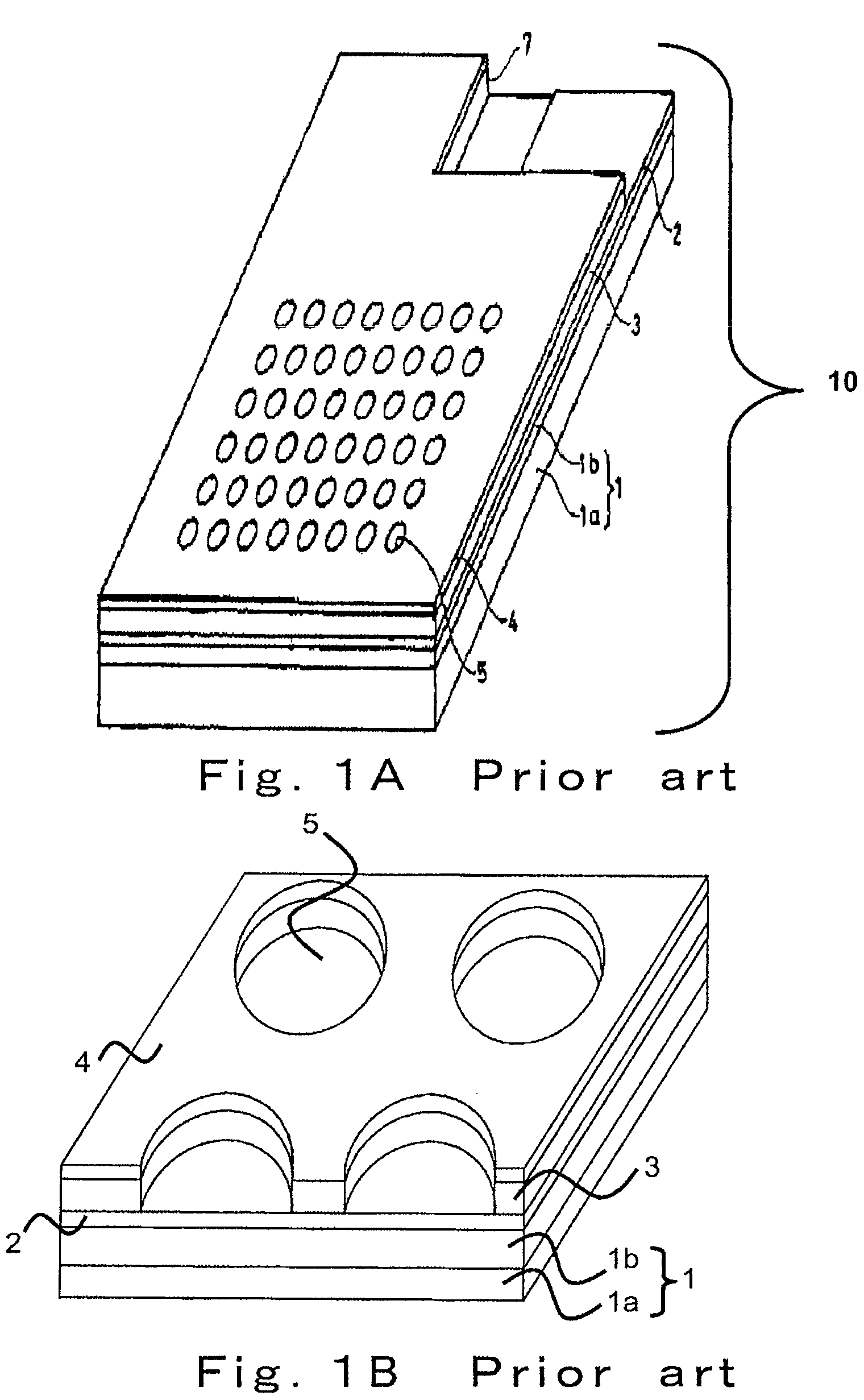
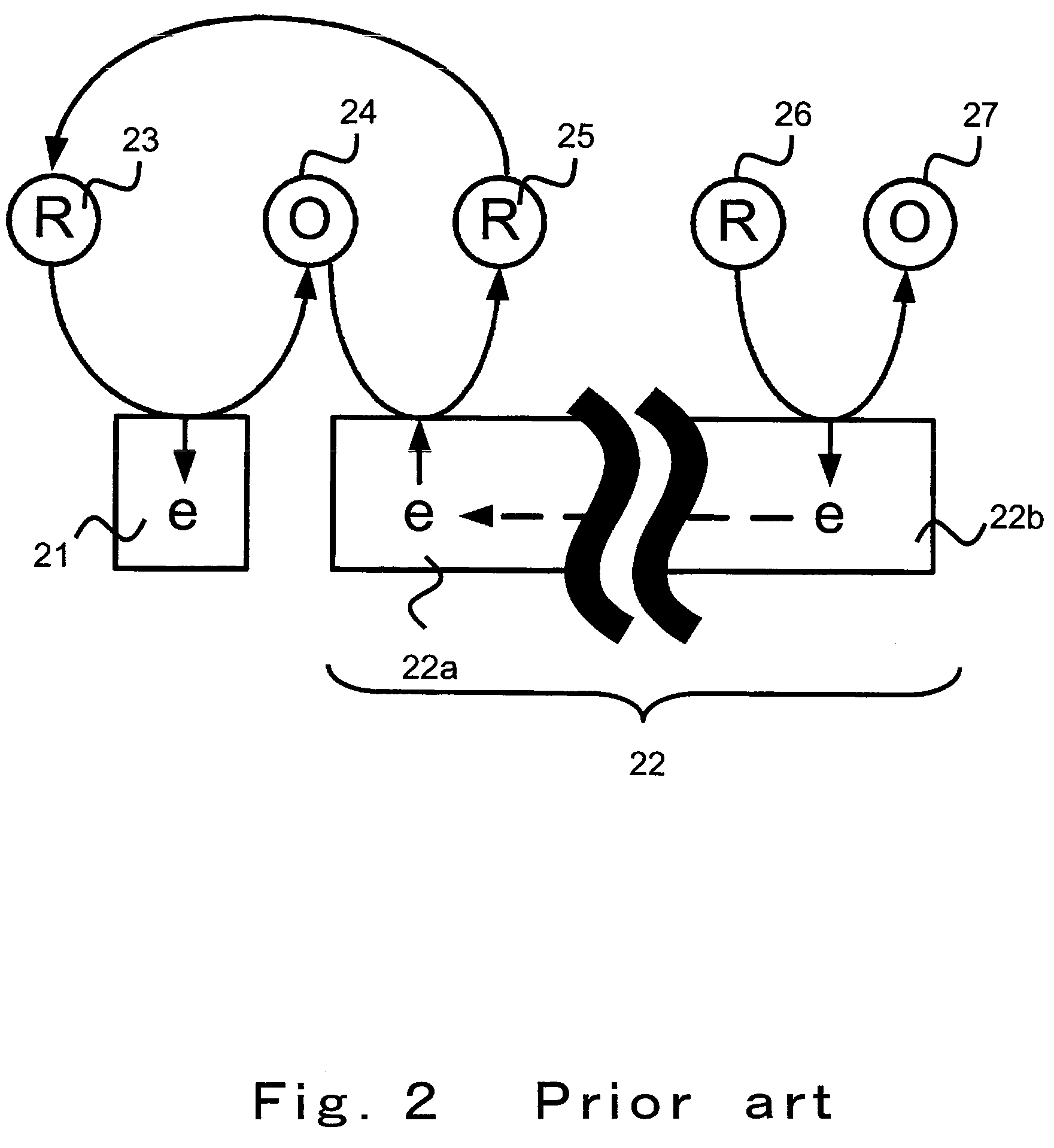
As shown in FIG. 1A and FIG. 1B, by providing surface electrode 4 that functions as a reduction electrode to have an area much greater than the area of bottom electrode 2 that functions as an oxidation electrode, a self-induced redox cycle is generated; however, this event may cause a problem as in the following.

Method used


Image

  • Electrode plate for electrochemical measurements
  • Electrode plate for electrochemical measurements
  • Electrode plate for electrochemical measurements

Examples


embodiment 1

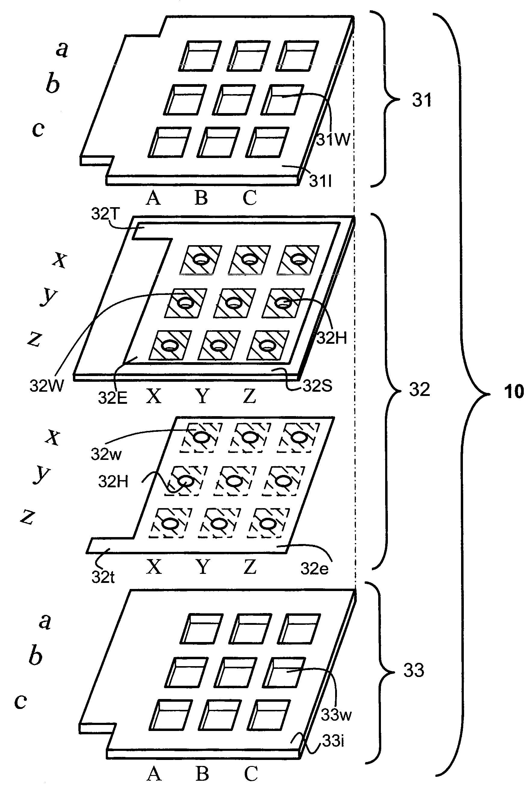
[0095]FIG. 3 shows an exploded perspective view illustrating an electrode plate for electrochemical measurements according to this Embodiment 1.

[0096]As shown in FIG. 3, the electrode plate for electrochemical measurements 10 according to this Embodiment 1 is constructed by laminating lower layer 33, substrate 32, and upper layer 31 in this order from the downside. Both the lower layer 33 and the upper layer 31 are insulators.

[0097]The substrate 32 is constituted with a body of the substrate 32S made of an insulator. Oxidation electrode plate 32E is provided on the superior face of this body of the substrate 32S, while reduction electrode plate 32e is provided on the inferior face of this body of the substrate 32S. The oxidation electrode plate 32E is sandwiched between the body of the substrate 32S and the upper layer 31, as shown in FIG. 3. Similarly, the reduction electrode plate 32e is sandwiched between the body of the substrate 32S and the lower layer 33.

[0098]The upper layer ...

embodiment 2

[0144]As shown in FIG. 11, mesh filter 111M is provided on the superior face of the upper layer 31 in this Embodiment 2.

[0145]When a plasma component separated from blood is used as a sample solution used in the measurement, hardened blood clot, haemocyte components, protein components and the like which failed to separate and contaminated may block the through-hole 32H.

[0146]In order to avoid such an inexpedience, the sample solution is fed to the electrode via filtration with a filter outside the electrode system. In addition, blocking of the through-hole 32H with blood clot and the like can be prevented by forming the filter 111M having a filtrating function on the upper layer 31.

[0147]A filter (not shown in the Figure) may be also provided on the downside the lower layer 33 as needed.

embodiment 3

[0148]As shown in FIG. 13, not only the oxidation electrode plate 32E and the reduction electrode plate 32e, but also the reference electrode 131E and the auxiliary electrode 133e may be formed integrally in this Embodiment 3. According to this construction, miniaturization of the apparatus is enabled since addition of the reference electrode 42 and the auxiliary electrode 43 is not required as shown in FIG. 4.

[0149]The reference electrode 131E is preferably formed on the superior face of the upper layer 31. The reference electrode 133e is preferably formed on the inferior face of the lower layer 33.

[0150]When the electrode plate for electrochemical measurements demonstrated in this Embodiment 3 is provided with the filter demonstrated in Embodiment 2 is provided, the reference electrode 131E may be provided upside the filter 111M, or to the contrary, the reference electrode 131E may be provided downside the filter 111M.

[0151]In the description of Embodiments 1 to 3, the oxidation e...


PUM

PropertyMeasurementUnit
areaaaaaaaaaaa
areaaaaaaaaaaa
areaaaaaaaaaaa

Abstract

An object of the invention is to provide an electrode plate for electrochemical measurements for detecting with high sensitivity and determining a substance included in a living body. The electrode plate of the present invention has on both faces of body of the substrate, oxidation electrode and reduction electrode opened respectively at upper layer opening and lower layer opening having the same area; and further has a plurality of through-holes that penetrate through from the face of the oxidation electrode to the face of the reduction electrode, in which electrode pairs are formed which exhibit a redox cycle effect between the oxidation electrode and the reduction electrode by applying the potential which can proceed an oxidative reaction of a reductant on the oxidation electrode, and the potential which can proceed a reductive reaction of an oxidant on the reduction electrode.

Description

[0001]This Application is a continuation of International Application No. PCT / JP2008 / 001893, whose international filing date is Jul. 15, 2008 which in turn claims the benefit of Japanese Patent Application No. 2007-189006, filed on Jul. 20, 2007, the disclosures of which Applications are incorporated by reference herein.BACKGROUND OF THE INVENTION[0002]1. Field of the Invention[0003]The present invention relates to an electrode plate for electrochemical measurements for detecting with high sensitivity and determining quantitatively a substance included in a living body in a slight amount.[0004]2. Related Art[0005]In recent years, electrode plates for electrochemical measurements for quantitatively determining the concentration of a saccharide such as sucrose, glucose or the like included in blood in a living body by a combination of a specific catalytic action of an enzyme and an electronic mediator having an electrode reaction activity.[0006]According to such an electrode plate for...

Claims


Application Information

Patent Timeline
Patent Type & Authority Patents(United States)
IPC IPC(8): G01N27/30
CPCG01N27/3277
Inventor SASAKI, HIDEHIROOKI, AKIO
Owner PANASONIC CORP
Learn More