
Differential pressure sense die based on silicon piezoresistive technology

a technology of silicon piezoresistive technology and differential pressure sensor, which is applied in the direction of fluid pressure measurement by mechanical elements, instruments, measurement devices, etc., can solve the problems of limited ability to achieve high accuracy of sensing low differential pressure over temperature, limit sensor performance, etc., and achieve high-performance differential pressure sensors.

Active Publication Date: 2010-01-12
HONEYWELL INT INC
View PDF8 Cites 34 Cited by
  • Summary
  • Abstract
  • Description
  • Claims
  • Application Information

AI Technical Summary

Benefits of technology

The present invention provides an improved sensor method and system that can measure low differential pressures in harsh duty applications such as automotive engines. The sensor is designed and configured based on a unique silicon piezoresistive technology and can be utilized in EGR systems and devices. The sensor is protected from exposure to sensed media and attack from acids and abrasive chemicals through a top cap and optional constraint for stress relief. The sensor can be bonded to a substrate with standard die attach materials and microelectronic packaging processes to yield a high performance differential pressure sensor.

Problems solved by technology

However, the problem associated with this type of configuration is that the wire bond pads and the topside of the sense die have to be exposed to the sensed media.
The problem associated with this configuration is that the sensors utilize two separate pressure diaphragms and the ability to achieve high accuracy of sensing low differential pressures over temperature is limited.
Therefore each pressure die provides a unique transfer function and the outputs do not match over temperature, which limits the sensor performance.

Method used


Image

  • Differential pressure sense die based on silicon piezoresistive technology
  • Differential pressure sense die based on silicon piezoresistive technology
  • Differential pressure sense die based on silicon piezoresistive technology

Examples


Embodiment Construction

[0020]The particular values and configurations discussed in these non-limiting examples can be varied and are cited merely to illustrate at least one embodiment and are not intended to limit the scope thereof.

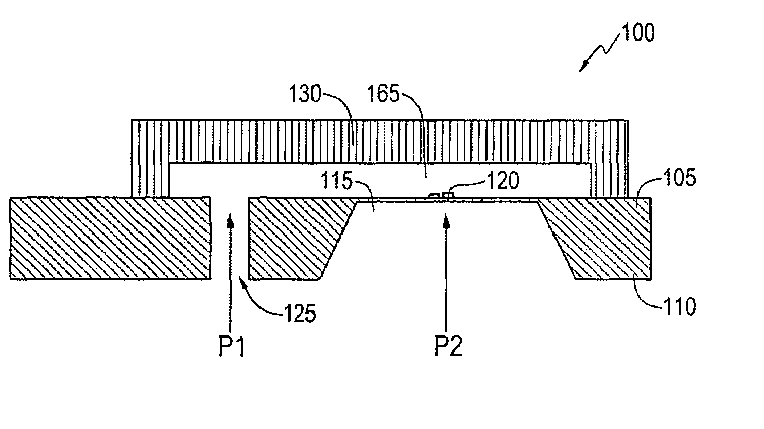
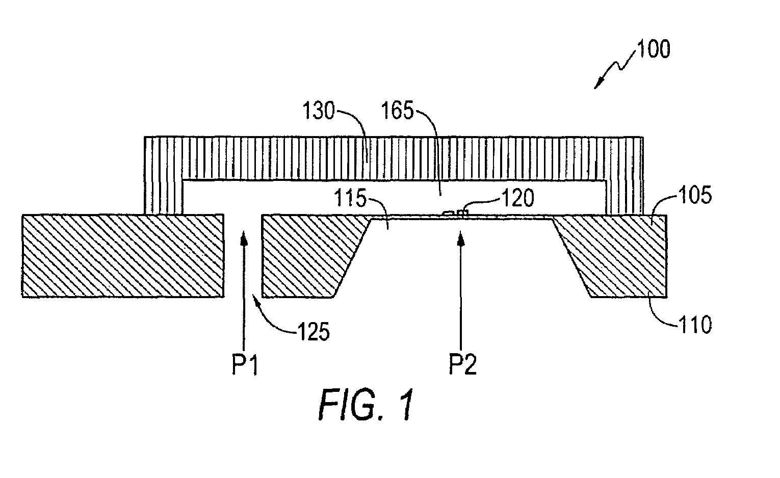
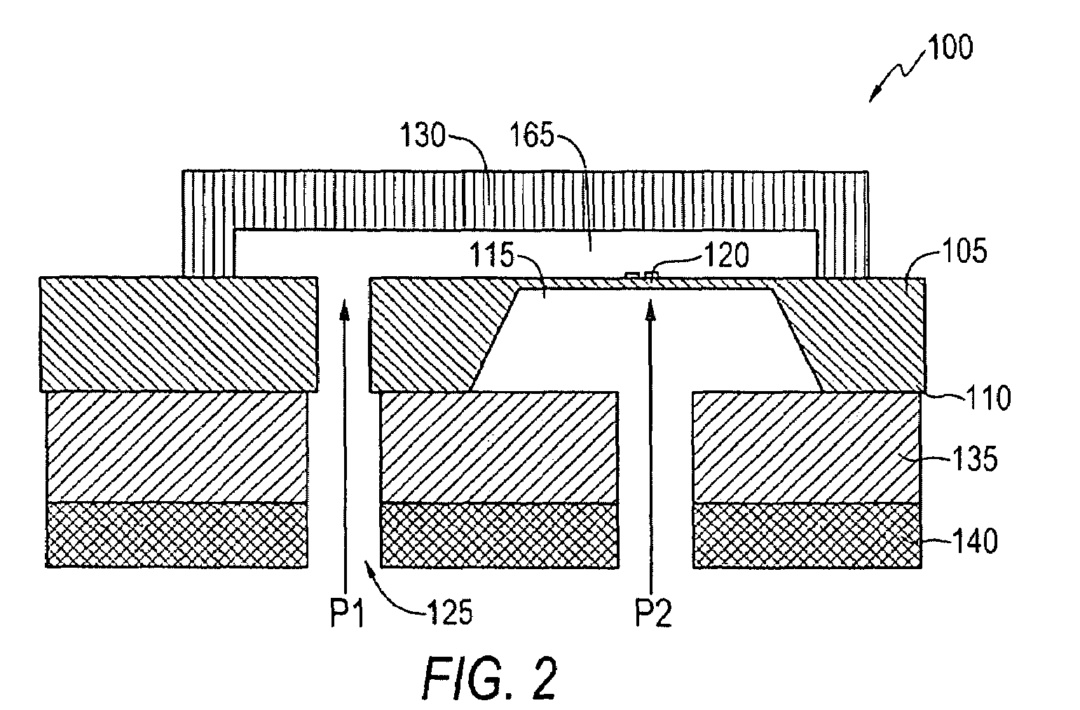
[0021]A differential micromachined pressure sense die utilizing silicon piezoresistive technology is disclosed herein. In such a device, a differential pressure sensor with high isolation between the sensed media and the sensor's electronics can be implemented. Such a sensor can be utilized, for example, to sense the exhaust pressure on automotive engines. Referring to FIG. 1, a cross sectional view of single differential pressure sense die 100 with a hole is illustrated, in accordance with a preferred embodiment. Note that in FIGS. 1-6, identical or analogous parts or elements are generally indicated by identical reference numerals. The sense die 100 generally includes a front side 105 and a backside 110.

[0022]A diaphragm 115 can be etched from the pressure sense die 100 such ...


PUM

PropertyMeasurementUnit
pressureaaaaaaaaaa
pressuresaaaaaaaaaa
stressaaaaaaaaaa

Abstract

A method and apparatus for designing a differential pressure sense die based on a unique silicon piezoresistive technology for sensing low differential pressure in harsh duty applications is disclosed. The pressure sense die comprises of an etched pressure diaphragm and a hole that is drilled through the sense die wherein the pressure sense die possess a backside and a front side and are associated with varying pressures. A top cap can be attached to the front side and an optional constraint for stress relief can be attached to the backside of the differential pressure sense die. The top cap and the constraint comprise of glass and / or silicon and can be attached with an anodic bonding process or glass frit process.

Description

TECHNICAL FIELD[0001]Embodiments are generally related to sensor methods and systems. Embodiments are also related to differential back pressure sensors. Embodiments are additionally related to differential pressure sense die designs for sensing low differential pressures with respect to a high common mode pressure.BACKGROUND OF THE INVENTION[0002]EGR (Exhaust Gas Recirculation) systems are employed in automotive vehicles in order to help reduce various engine emissions. Such systems typically employ an EGR valve that is disposed between the engine exhaust manifold and the engine intake manifold, and operable, when in an open position, to re-circulate a portion of the exhaust gases from the exhaust side of the engine back to the intake side. The amount of exhaust gas re-circulation (EGR) is determined by the EGR valve, which is controlled by the engine computer. A typical EGR valve configuration using vacuum control utilizes an electrically actuated vacuum regulator (EVR) and a diff...

Claims


Application Information

Patent Timeline
Patent Type & Authority Patents(United States)
IPC IPC(8): G01L7/00
CPCG01L13/025
Inventor RICKS, LAMAR F.
Owner HONEYWELL INT INC
Learn More