Devices having a textured surface

Active Publication Date: 2010-01-12
MENTOR WORLDWIDE
45 Cites 58 Cited by

AI-Extracted Technical Summary

Problems solved by technology

In general, the textured surface is created by applying two or more lay...

Benefits of technology

[0014]Because the particles are coated with a polymer dispersion after they are applied to the surface of the device, the particles are firmly attached to the device. Moreover, while the textured surface is irregular, it is relatively free of sharp edges because the polymer dispersion applied to the particles coats the particles and creates somewhat gently rounded edges. The textured surface includes cavities, interstices and, in some cases, tunnels or passageways. The cavitie...

Abstract

A method for forming a randomly textured surface on an implantable device such as soft tissue prosthesis. The textured surface has numerous cavities, interstices and passageways or tunnels and is thus referred to as a microporous surface texture. The surface is formed by two or more applications of polymeric particles and a polymeric dispersion.

Application Domain

Technology Topic

Image

  • Devices having a textured surface
  • Devices having a textured surface
  • Devices having a textured surface

Examples

  • Experimental program(1)

Example

Example
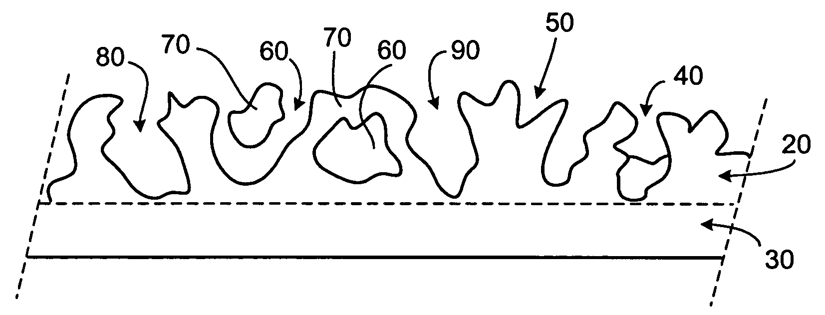
[0044]A mammary prosthesis having a microporous surface texture can be prepared as follows. An elastomeric shell is formed by conventional dip-molding in an HTV silicone dispersion using an appropriately sized and shaped mandrel. After each dip, solvent is allowed to evaporate so that the new silicone layer is stabilized. The stabilization or solvent evaporation can be accelerated by heating (e.g., heating at 120° F. for 15 minutes). This process is repeated until a shell having the desired thickness is formed. After the last layer of silicone is applied, the shell can be partially or fully cured. While it is desirable to allow solvent to evaporate from the shell, it can be desirable to not cure the shell at all. The tackiness of an uncured silicone shell fosters adhesion of the solid particles. Once the shell has been formed, particles of fully cured HTV silicone having an average diameter of 100 microns are applied to the surface of the shell. Because the surface of the shell is tacky and because the particles have a static charge, the particles adhere readily. The particles can be applied at a density that allows almost complete coverage of the shell or partial coverage. Thus, the particles can be applied relatively densely so that there is little exposed shell or they can be applied relatively sparsely so that there is considerable exposed shell. In addition, as described in greater detail below, the particles can be applied to only a portion of the shell. The shell is heated (e.g., at 250-325° F. for 30 to 60 minutes) to partially cure or gel the silicone layer to which the particles are adhered. Particles that do not adhere to the shell can be removed by gently blowing air over the surface of the shell or by some other method. The shell is then dipped into a silicone dispersion (e.g., HTV silicone diluted 10% to 13% solids with xylene, toluene, tetrahydrofuran or some other suitable solvent) to apply a particle coating layer that envelops the applied particles. After excess silicone dispersion has been allowed to run off and the solvent has substantially or completely evaporated, the particle coating layer is partially cured or gelled (e.g., by heating to 250-325° F. for 30 to 60 minutes). The application of particles, curing, coating with silicone dispersion and curing is repeated two more times for a total of three application of particles and three applications of silicone dispersion. Finally, the shell is fully cured.
[0045]To create a complete mammary prosthesis, the now textured shell must be sealed. To do so, the shell is stripped from the mandrel. The opening in the posterior face of the shell is sealed using a patch comprising a cured layer of silicone sheeting and an uncured layer of silicone. The patch is shaped and sized to be somewhat larger than the opening in the posterior face of the shell and can include a filling valve. The patch is positioned inside the shell such that the uncured layer of the patch faces outward and the perimeter of the patch overlaps the edge of the shell surrounding the opening. The assembly is compressed either between hot platens at, e.g., 325° F. and 60 p.s.i. or platens at room temperature and 60 p.s.i. for about two to three minutes. The patched shell is then heated in an oven at 325° F. for about one half hour to cure fully.
[0046]In the case of a tissue expander, the shell can be provided with a remote or integral valve that permits periodic addition of filling liquid after the tissue expander has been implanted. For example, a needle can be used to pierce the skin and a self-sealing valve to add filling liquid to the device.
[0047]As noted above, the textured surface can be applied to all or only a portion of a device, e.g., a mammary prosthesis. For example, referring to FIG. 4, which shows a cross-section view of the shell 90 of a mammary prosthesis of the invention. The shell has an anterior face region 100, a posterior face region 110, an upper pole region 120 (i.e., the upper half of the shell when the prosthesis recipient is standing), a lower pole region 130 (i.e., the lower half of the shell when the prosthesis recipient is standing), an inner surface 140, an outer surface 150, a patch 160 and a filling port or valve 170 located on the posterior face region of the prosthesis. The posterior face region 110 of the shell is placed against the patient's chest wall when the prosthesis is implanted. It can be desirable to apply texture to the entire outer surface of the shell, only to the anterior face region, only to the posterior face region, only to the upper pole region (or the upper pole region of the anterior face), only the lower pole region (or the lower pole region of the anterior face) or to two or more regions or to the entire shell. It may also be desirable to apply more layers of particles to some regions of the shell than to others.
Other Embodiments
[0048]A soft tissue prosthesis can have any desired shape, e.g., the shell of the prosthesis can be circular, oval, or crescent shaped. The prosthesis can have a single lumen or multiple lumens. It can be formed of silicone, a laminate of various forms of silicone, silicone copolymers, polyurethane, and various other elastomers in various combinations. Various materials are described in U.S. Pat. Nos. 4,592,755 and 4,205,401.
[0049]The shell can be filled with a fluid or gel. In addition, an amount of solid material can be combined with the fluid or gel to adjust the density or compressibility of the filling.
[0050]The particles applied to create the textured surface can be formed of a non-polymeric material, e.g., they can be formed from any solid material.
[0051]The prosthesis of the invention can be provided as a kit with a shell and a means for filling the shell, e.g., a syringe. The kit can further include an adapter tube for connecting the syringe to the filling port of the shell.
[0052]A number of embodiments of the invention have been described. Nevertheless, it will be understood that various modifications may be made without departing from the spirit and scope of the invention.

PUM

PropertyMeasurementUnit
Fraction0.08fraction
Fraction0.13fraction
Fraction0.06fraction
tensileMPa
Particle sizePa
strength10

Description & Claims & Application Information

We can also present the details of the Description, Claims and Application information to help users get a comprehensive understanding of the technical details of the patent, such as background art, summary of invention, brief description of drawings, description of embodiments, and other original content. On the other hand, users can also determine the specific scope of protection of the technology through the list of claims; as well as understand the changes in the life cycle of the technology with the presentation of the patent timeline. Login to view more.

Similar technology patents

Foamable hot melt adhesive composition and uses thereof

ActiveCN101402834AHigh thermal pressure bonding strengthGood adhesionLaminationLamination apparatusChemistryHot-melt adhesive
Owner:GUANGZHOU LUSHAN NEW MATERIALS +1

Classification and recommendation of technical efficacy words

Why Eureka
Try Eureka