Multifunction all in one capture station for creating identification documents

a multi-functional, identification document technology, applied in the field of capture stations, can solve the problems of increasing the physical space occupied by separate devices, increasing costs and inconvenience, and affecting the efficiency of the capture station,

Active Publication Date: 2010-01-12
L 1 SECURE CREDENTIALING
View PDF32 Cites 78 Cited by
  • Summary
  • Abstract
  • Description
  • Claims
  • Application Information

AI Technical Summary

Benefits of technology

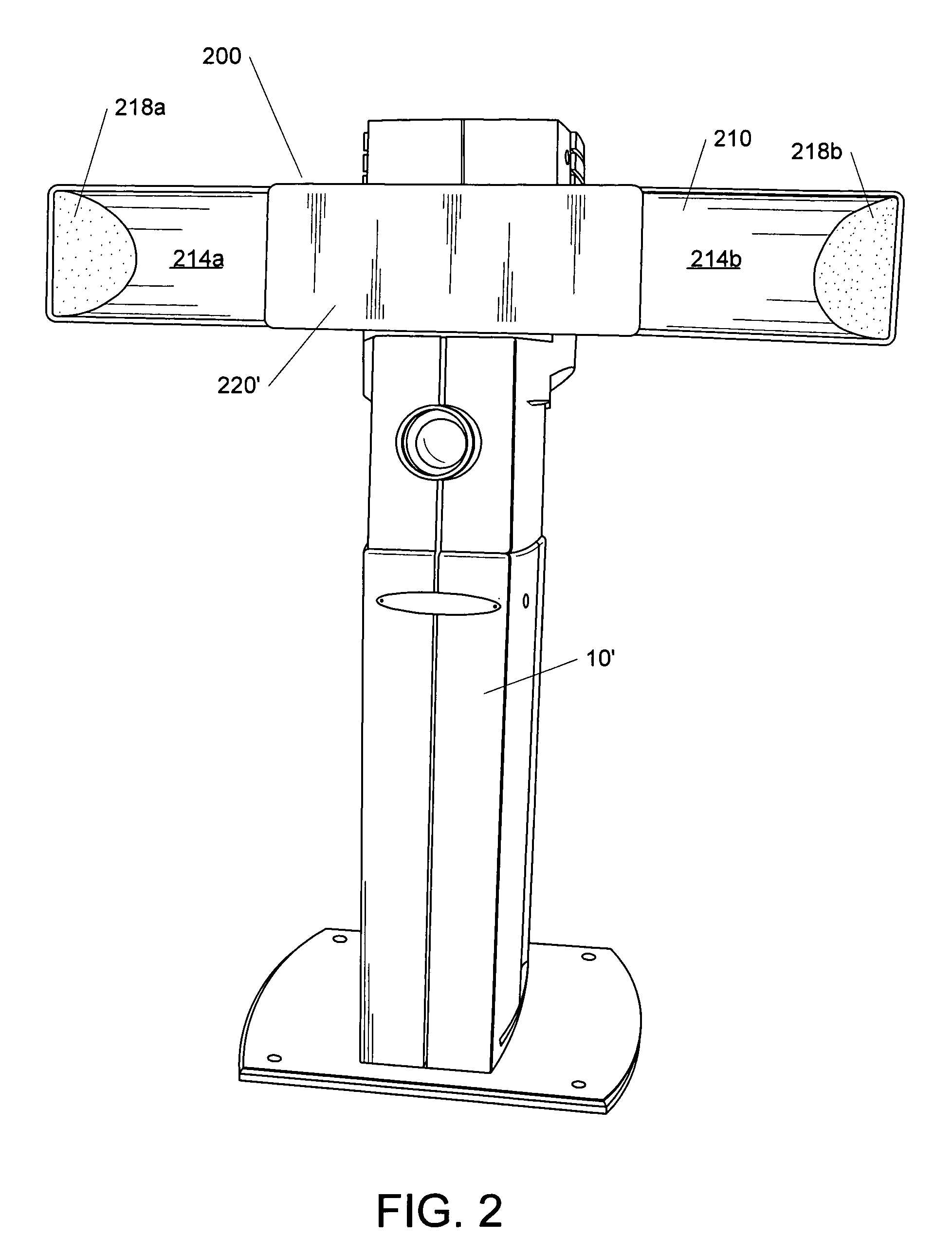
[0028]As explained in the All In One Application, the capture station 10 of FIG. 1 can be provided with a lighting device 200, as shown in the capture station 10′FIG. 2. As described in a commonly assigned patent application entitled “Enhanced Shadow Reduction System and Related Techniques for Digital Image Capture,” Ser. No. 10 / 663,439, filed Sep. 15, 2003 (hereinafter “Shadow Reduction Application”), which is hereby incorporated by reference, the lighting device 200 can be used to help reduce shadows in subjects whose images are being captured using the capture station 10′. The lighting device 200 includes a housing 210 which includes diffusely reflective inner surfaces 214a and 214b coupled to diffusely reflective end portions 218a and 218b, respectively. The lighting device 200 further includes a diffuser 220 disposed on the housing 210. A reflector 222 is not visible in FIG. 1, but the reflector 222 and additional details about the lighting device 200 are described more fully in the Shadow Reduction Application.
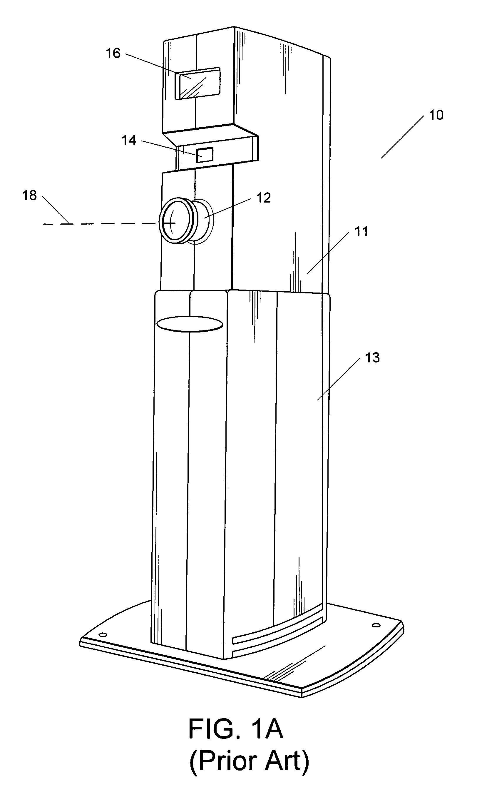
[0033]Although the capture station 10 of FIG. 1 meets at least some of the needs of users, it would be desirable to further reduce the footprint of the capture station 10 and, if possible, combine the capture station with a computer and include with (or couple to) the capture station one or more other devices for acquiring information about a subject. It also would be desirable to provide a capture station that is simple to set up and use, and which is readily configurable based on the end user's needs. It would be advantageous if a capture station could be provided that can help to minimize the problems associated with hanging wires and connections. It also would be desirable to have a capture station with a streamlined, contemporary, and aesthetically pleasing appearance, which can be simpler to install, upgrade, and maintain than some current installations.
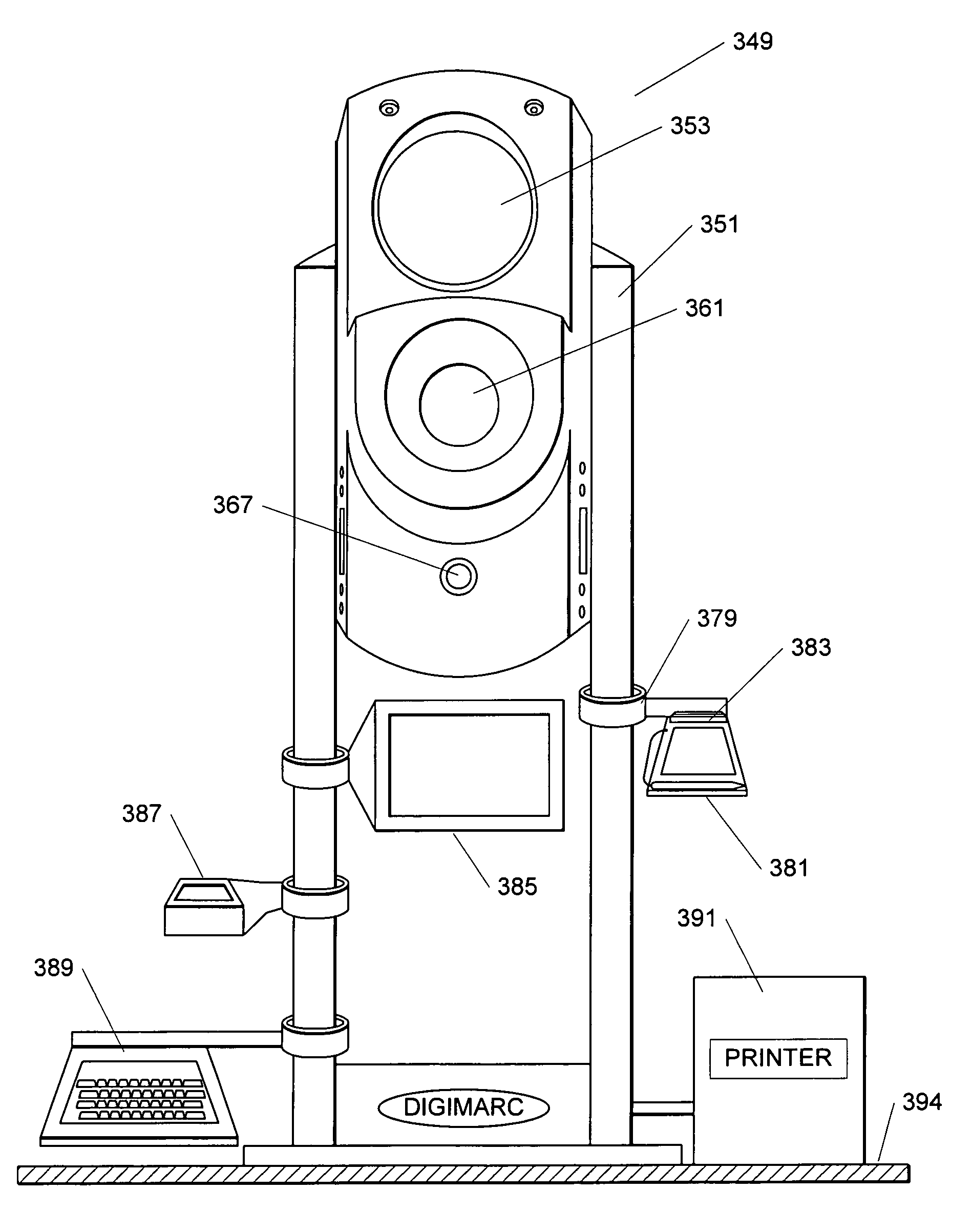
[0035]In another embodiment, the invention provides an all in one capture station that includes a camera stand, camera mounted within the camera stand, an integrated lighting system, and an optional computer integrated into the camera stand. The camera stand has one or more elongated support members to which additional optional capture elements (e.g., a signature pad) can be fixedly coupled. In at least one embodiment, the elongated support members are constructed and arranged so that connections (e.g., cables) between the camera, computer, and / or the additional capture element(s) can be routed through the elongated members. This embodiment of the all in one capture station can provide a number of functional, operational, aesthetic, and / or economic advantages, including:
[0038](c) ability to quickly and easily customize features of the capture station; and

Problems solved by technology

This type of capture configuration is more difficult to transport and configure in an office setting and is more costly because it involves multiple physically separate machines or devices.
In addition, the separate devices often take up a significant amount of physical space in what often is a space constrained environment.
This arrangement also presents challenges in sharing the capture station among more than one station operator, adding cost and inconvenience.
However, this configuration presents more costs and challenges because all capture control commands and associated data flow from a source workstation to a destination workstation connected to the camera assembly, and the destination workstation may not always be available.
A typical problem is where the destination workstation is not logged on due to the absence of office personnel responsible for that station.
In this case, the workstation is not able to process requests for image capture and transfer from other workstations.
Another limitation of known systems for capturing images is that such systems can be awkward to adjust to accommodate photographing subjects of varying heights.
Some known systems couple the camera directly to a computer monitor, limiting the range of motion and adjustment of the camera.
Use of conventional tripods can be inconvenient and awkward in some types of environments, however, such as locations for taking images used in identification documents.
One problem is that such locations are often space limited and tripods can be bulky and space-consuming.
Another problem is that it can be difficult and time-consuming for an operator to adjust all three legs of the conventional tripod quickly and easily to the proper length needed to mount the camera at a desired elevation, which elevation may change with each person being photographed.
Stability and balance of the tripod can also be an issue, especially since the legs each must be at approximately the same length.
Another issue is theft prevention: because it is not simple or even desirable to rigidly mount a tripod and camera in a fixed location, the tripod and camera may have to be disassembled and reassembled with each days use, including connections to computers, printers, etc., which is time-consuming, prone to error, and prone to accidental damage of the equipment.

Method used


Image

  • Multifunction all in one capture station for creating identification documents
  • Multifunction all in one capture station for creating identification documents
  • Multifunction all in one capture station for creating identification documents

Examples


Embodiment Construction

Terminology

[0087]In the foregoing discussion, the use of the word “ID document” is broadly defined and intended to include all types of ID documents, including (but not limited to), documents, magnetic disks, credit cards, bank cards, phone cards, stored value cards, prepaid cards, smart cards (e.g., cards that include one more semiconductor chips, such as memory devices, microprocessors, and microcontrollers), contact cards, contactless cards, proximity cards (e.g., radio frequency (RFID) cards), passports, driver's licenses, network access cards, employee badges, debit cards, security cards, visas, immigration documentation, national ID cards, citizenship cards, social security cards, security badges, certificates, identification cards or documents, voter registration and / or identification cards, police ID cards, border crossing cards, security clearance badges and cards, legal instruments, gun permits, badges, gift certificates or cards, membership cards or badges, and tags. Also...


PUM


Abstract

A capture station for creating identification documents comprises a housing including a camera and lighting device, a base, and at least one leg extending from the base. The housing is mounted to the leg to enable height adjustment of the camera. One configuration of the capture station has two substantially rigid and parallel legs with the housing mounted between the legs. Configurations of the capture station can include a processor, such a CPU or embedded controller, enabling ID document data capture functions to be executed within the capture station, and to be controlled via a remote computer via a network connection. In one embodiment, the processor is housed in the base and communicates with the camera via wiring routed through the leg. Peripherals used in capture functions, such as a fingerprint reader, signature pad, display, etc., may be mounted to the leg via clamps, or a plug in receptacle with power and communication wiring provided in the leg.

Description

RELATED APPLICATION DATA[0001]This application claims priority from U.S. Provisional Application 60 / 564,820 filed Apr. 22, 2004.[0002]This application is also a continuation in part of the following U.S. patent applications:[0003]U.S. application Ser. No. 10 / 676,362, filed Sep. 30, 2003 (U.S. Patent Publication 20050068420);[0004]U.S. application Ser. No. 10 / 663,439, filed Sep. 15, 2003 (U.S. Patent Publication 20040140459; and[0005]PCT Application No. PCT / US2004 / 032699, filed Sep. 30, 2004 (PCT Publication WO 2005 / 034012.[0006]Each of the above U.S. patent documents is herein incorporated by reference in its entiretyTECHNICAL FIELD[0007]The invention relates to a capture station and related systems and methods for capturing information used for creating identification documents. This invention also relates to a configurable capture station structure that integrates together a computer with one or more components, such as cameras, signature pads, fingerprint scanners, etc., used to ...

Claims


Application Information

Patent Timeline
Patent Type & Authority Patents(United States)
IPC IPC(8): H04N5/225G03B17/00H04N5/232H04N7/18G06K9/00H04N1/00
CPCH04N1/00127H04N1/00559H04N1/00562H04N1/00519H04N2201/0056H04N2201/0063H04N2201/0084
Inventor BOHAKER, DAVIDDUGGAN, CHARLES F.KENEN, LEO M.
Owner L 1 SECURE CREDENTIALING
Why Eureka
Try Eureka