Computerized workflow method for stent planning and stenting procedure

a technology of stent delivery and computerized workflow, which is applied in the field of planning a stent delivery procedure, can solve the problems of inability to achieve complete success on a long-term basis for many patients, inability to accurately place the stent delivery catheter, and lack of success in some patients

Active Publication Date: 2010-01-19
SIEMENS HEALTHCARE GMBH
View PDF5 Cites 93 Cited by
  • Summary
  • Abstract
  • Description
  • Claims
  • Application Information

AI Technical Summary

Benefits of technology

[0017]In the stenting procedure itself, the 2D real-time image of the lesion containing region, acquired with the C-arm fluoroscopy system, can be correlated with the planning image data set (i.e. the previously-acquired 3D image of the lesion-containing region). The optimized deployed position of the virtual representation of the selected stent can be overlaid on the real-time 2D image during the stenting procedure. In the stenting procedure, the actual stent is visualized in the subject in the real-time 2D image, and is manually brought into coincidence with the displayed optimal deployed position of the virtual representation. It is thus assured that the actual stent is placed in the subject at the optimal position and location that were determined using the simulation.

Problems solved by technology

Although stenting greatly enhances the patient's quality of life by relieving the patient's symptoms and reducing ischemia almost immediately, this technique has not proven to be completely successful on a long-term basis for many patients.
The lack of success in some patients is due to a phenomenon known as restenosis inside or near the stented area.
Again, foreshortening of 3D objects in the 2D x-ray projection can impair the correct placement of the stent delivery catheter.
At this point, the implanted stent cannot be removed and cannot even be shifted to a better location within the vessel.

Method used


Image

  • Computerized workflow method for stent planning and stenting procedure
  • Computerized workflow method for stent planning and stenting procedure
  • Computerized workflow method for stent planning and stenting procedure

Examples


Embodiment Construction

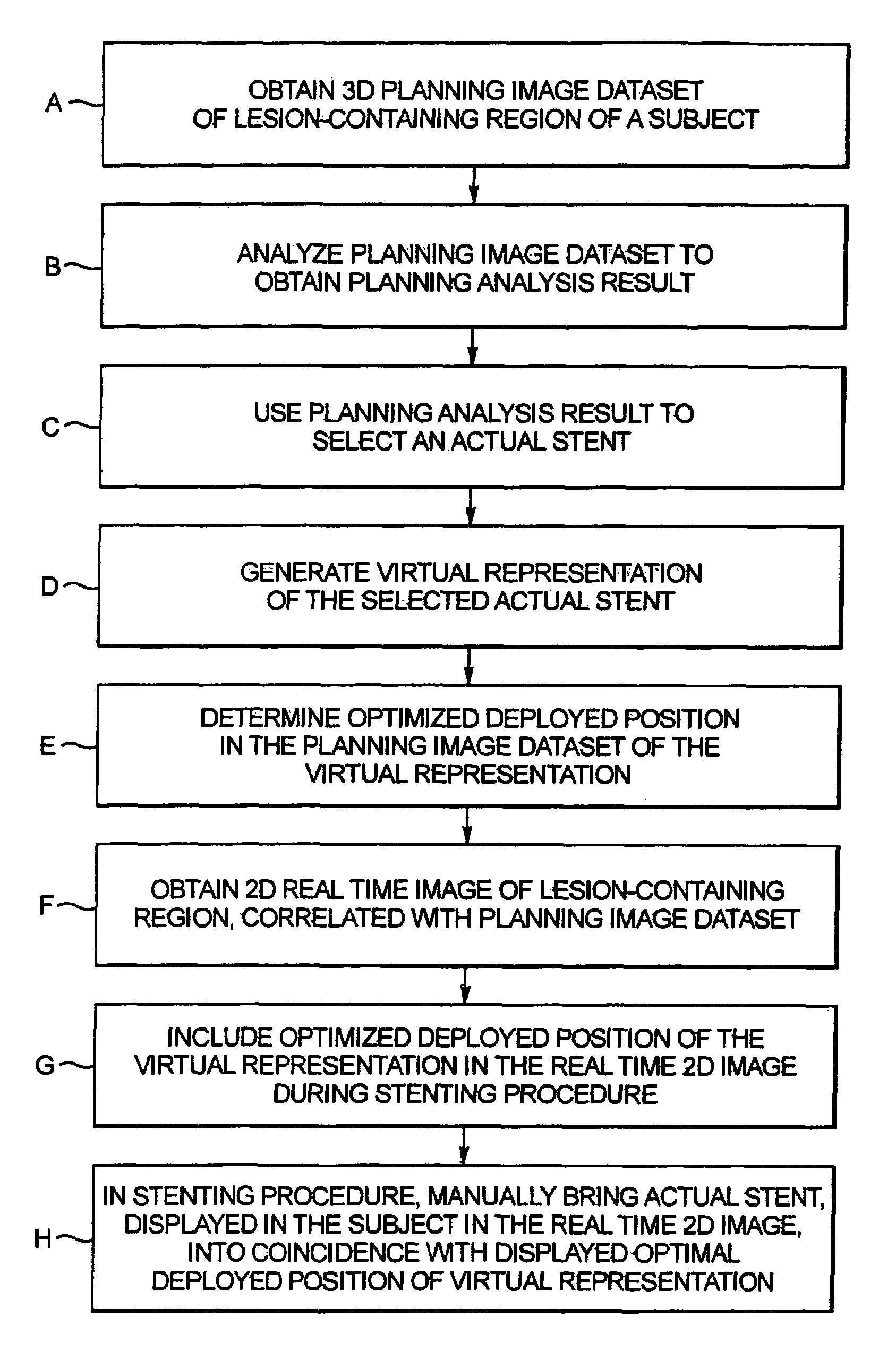
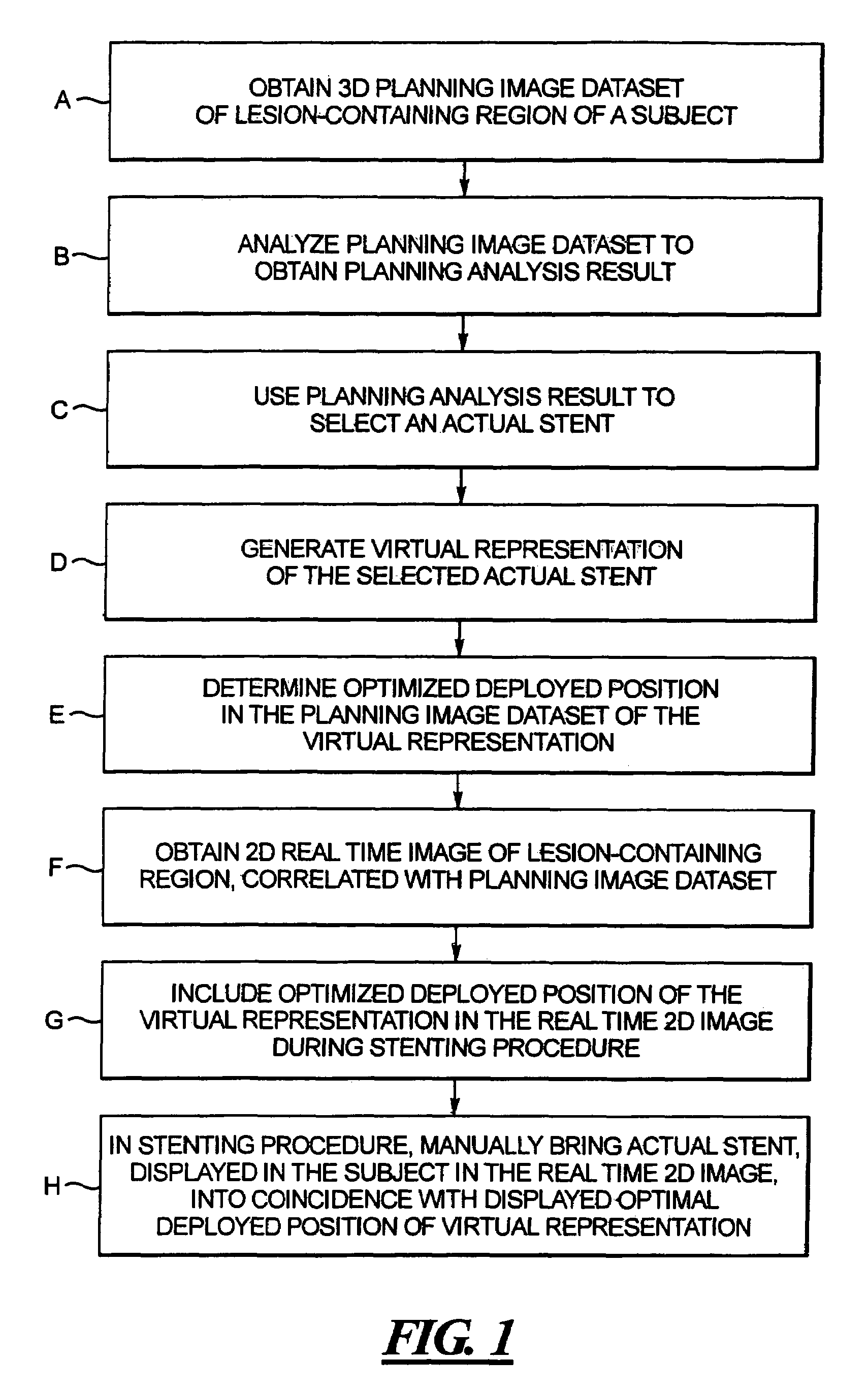
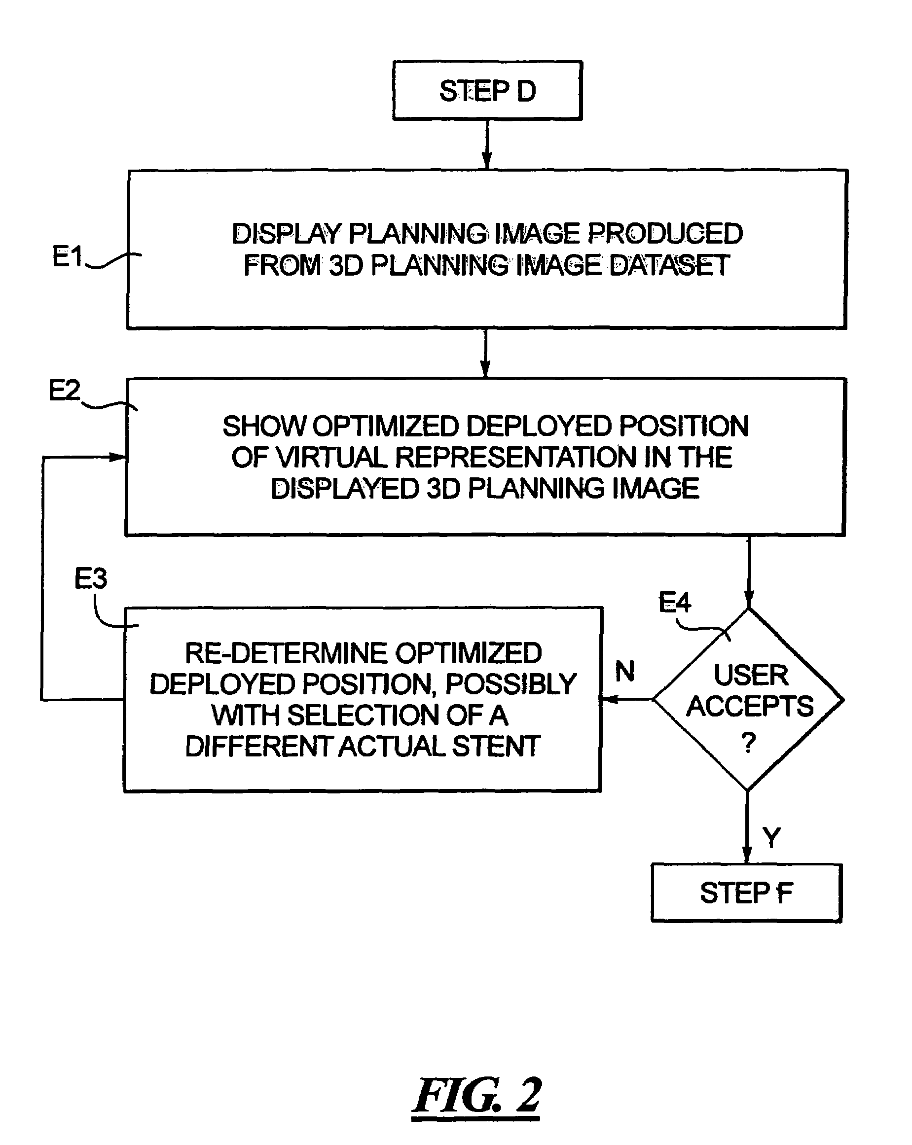
[0021]Certain basic steps in the inventive method are shown in the flow chart in FIG. 1, for computerized planning of a stenting procedure and computerized assistance in conducting the stenting procedure itself.

[0022]In step A, a 3D planning image data set is acquired of a lesion-containing region of a subject, and a 3D image is reconstructed from this data set in a known manner. The 3D image data set and image reconstruction can be undertaken using AXIOM Artis and Intervention Cardiac 3D (IC 3D), commercially available from Siemens AG. The data acquisition can be 3D or 4D. In this known data acquisition, an x-ray image of the diseased vessel, with contrast agent injection, is acquired with a C-arm system with the C-arm in a position to acquire the image in a first plane. The C-arm is then moved to a second angle position and the image of the diseased vessel, with contrast agent injection, is obtained in a second plane, different from the first plane. One of these images is then pre...


PUM


Abstract

In a computerized workflow method for stent planning and conducting a stenting procedure, characteristics of a lesion to be stented are determined from a 3D planning image of the region and selection of an actual stent for stenting the lesion is made with computer-assisted analysis of the lesion based on the characteristics. A virtual stent is electronically generated based on the actual stent, and, using the virtual stent, a best position for the actual stent, for effectively stenting the lesion, is determined. A real time 2D image of the lesion-containing region is displayed during the stenting procedure, with the virtual stent included therein at the aforementioned best position. A physician manually guides the actual stent relative to the lesion during the stenting procedure until the position of the actual stent, as seen in the displayed real time 2D image, coincides with the virtual stent in that image.

Description

BACKGROUND OF THE INVENTION[0001]1. Field of the Invention[0002]The present invention relates to techniques for planning a stenting procedure, including selection of an appropriate stent, and for conducting the stenting procedure, in which the stent is implanted in a subject at an appropriate location.[0003]2. Description of the Prior Art[0004]The use of percutaneous coronary interventions, particularly stenting procedures, has become the treatment of choice for many manifestations of coronary artery disease.[0005]Stenting procedures also are widely performed to treat stenosis in blood vessels other than the coronary arteries, such as the renal artery or the mesenteric artery, or other peripheral vessels.[0006]Although stenting greatly enhances the patient's quality of life by relieving the patient's symptoms and reducing ischemia almost immediately, this technique has not proven to be completely successful on a long-term basis for many patients. The lack of success in some patients...

Claims


Application Information

Patent Timeline
Patent Type & Authority Patents(United States)
IPC IPC(8): A61B5/05A61F2/82
CPCA61B6/481A61B6/504A61F2/82G06T19/006A61B90/36A61B5/0066A61B8/06A61B34/10A61B8/12
Inventor REDEL, THOMASCAMUS, ESTELLE
Owner SIEMENS HEALTHCARE GMBH
Why Eureka
Try Eureka