Means and method for the accurate placement of a stent at the ostium of an artery

a stenosis and stent technology, applied in the field of accurate placement of stents in stenosis, can solve the problems of difficult operation, limiting the injection of contrast materials, and limiting the passage of guide wires, balloon catheters, and/or stents, etc., to achieve accurate placement

Active Publication Date: 2010-01-26
MERIT MEDICAL SYST INC
View PDF15 Cites 64 Cited by
  • Summary
  • Abstract
  • Description
  • Claims
  • Application Information

AI Technical Summary

Benefits of technology

[0006]A first aspect of the present invention is an ostial stent positioner that has the form of a wire for most of its length and having a short cylinder with expandable legs situated at the positioner's distal end. The cylinder with its attached wire acts as an introducer sheath to introduce a stent delivery system with a stent into the artery that is to be stented. A second aspect of the present invention is a method for accurately placing a stent at the ostium of an artery that would have an ostial stenosis. Examples of such arteries that have ostial stenoses are the right and left main coronary arteries, a saphenous vein graft as used in coronary bypass surgery and the renal arteries. Each of these arteries has an ostium situated at the aorta.
[0009]The main object of this invention is to describe a means and method for accurately placing the proximal end of a stent within ±2 mm of the ostial plane of an artery that has a stenosis located at or near the ostium of that artery.
[0011]Still another object of the present invention is to teach a method for accurately placing a stent within an ostial stenosis.
[0012]Still another object of the present invention is to utilize a variable diameter slit cylinder to which the expandable legs are connected, which variable diameter cylinder is designed to expand radially outward so as to create gentle contact between the cylinder's outer surface and the interior surface of the guiding catheter.
[0014]Still another object of this invention is to have the wire that joins to the slit cylinder have a colored handle at its most proximal section and have a decreased wire thickness for the length of the wire that is closest to the slit cylinder so as to have increased flexibility at that portion that lies in the curved section of the guiding catheter.

Problems solved by technology

In such cases, the interventional cardiologist or radiologist is frequently unable to place the stent's proximal end within ±2 mm of the ostial plane.
However, the most important feature of such a device; namely, and expandable distal portion that touches the wall of the aorta near the ostium of the artery to be stented is not optimized for easy usage of such a device.
Such a design would have an incredible amount of friction between the cylindrical sheath and the interior wall of the guiding catheter that would make it very difficult to operate.
In addition, the Saltiel design would substantially obstruct the internal cross-section of the guiding catheter along its entire length, limiting the injection of contrast material, and the passage of guide wires, balloon catheters, and / or stents.
Such a design precludes an accurate stent positioning system that can be used with the stent delivery system of any manufacturer.

Method used


Image

  • Means and method for the accurate placement of a stent at the ostium of an artery
  • Means and method for the accurate placement of a stent at the ostium of an artery
  • Means and method for the accurate placement of a stent at the ostium of an artery

Examples


Embodiment Construction

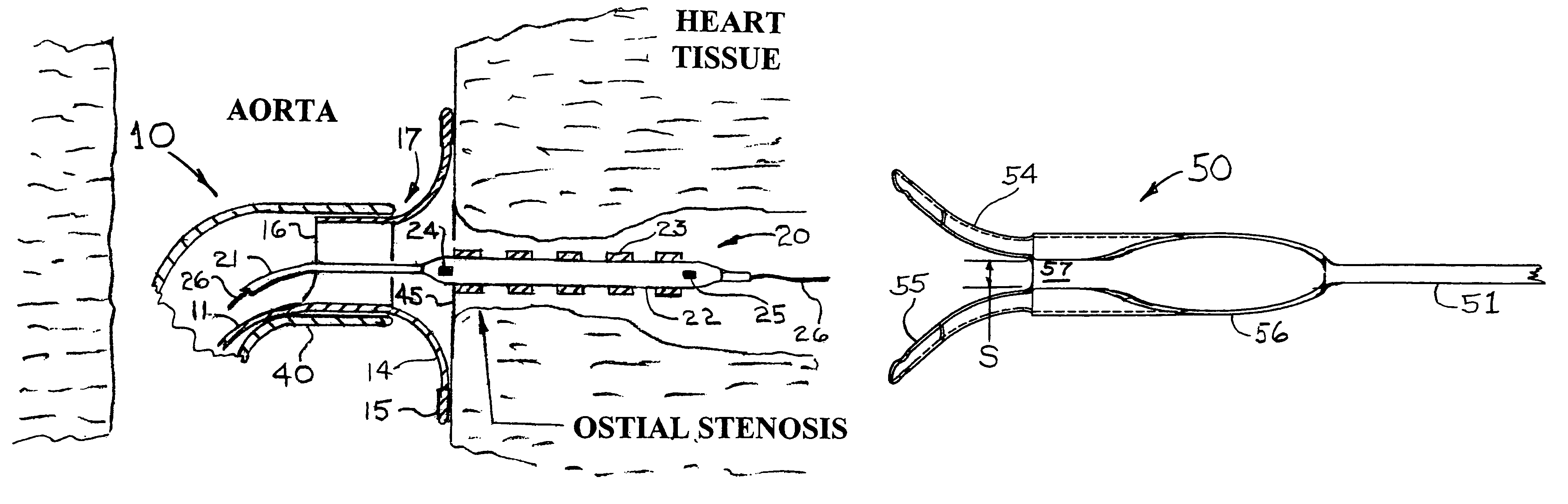
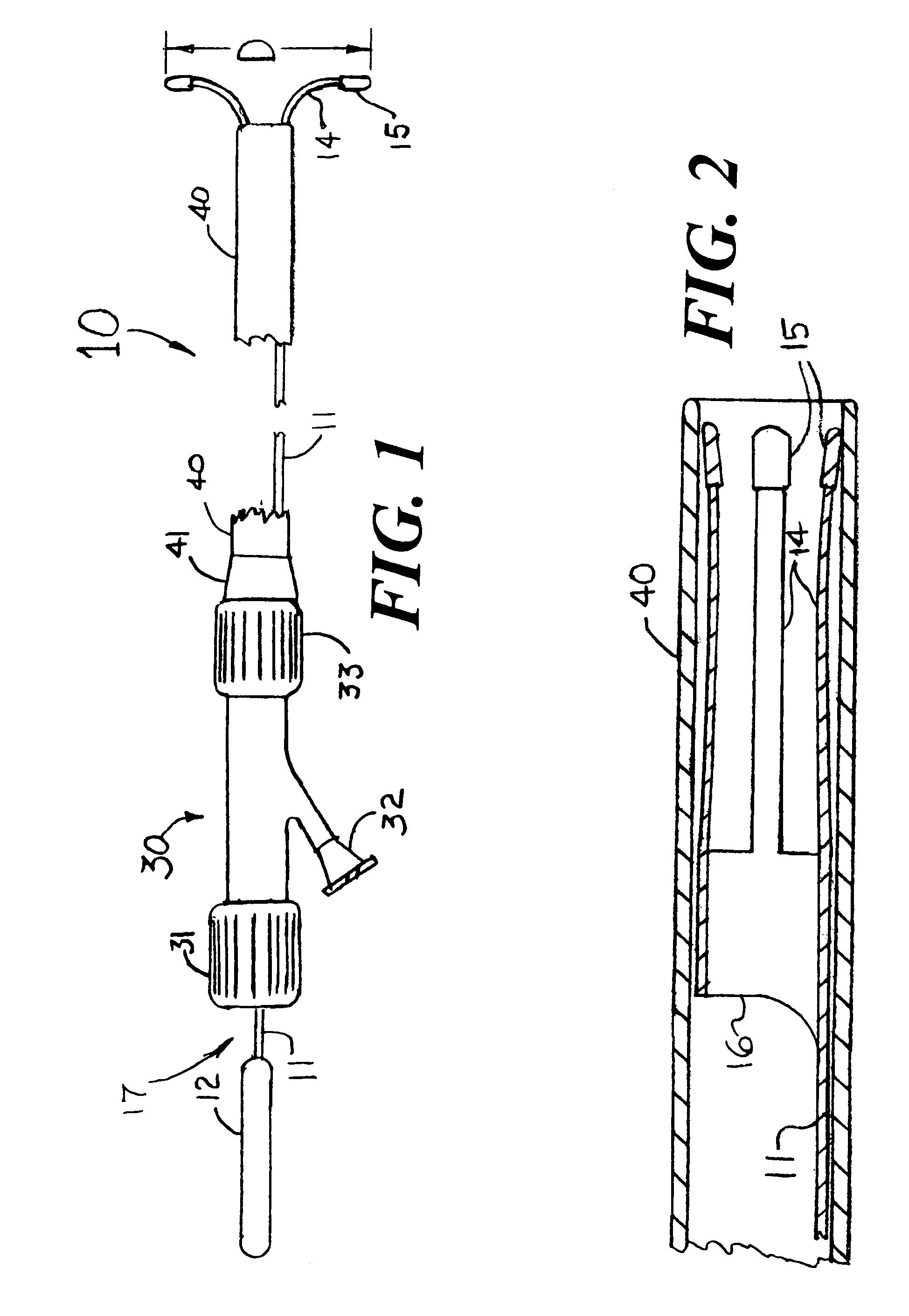
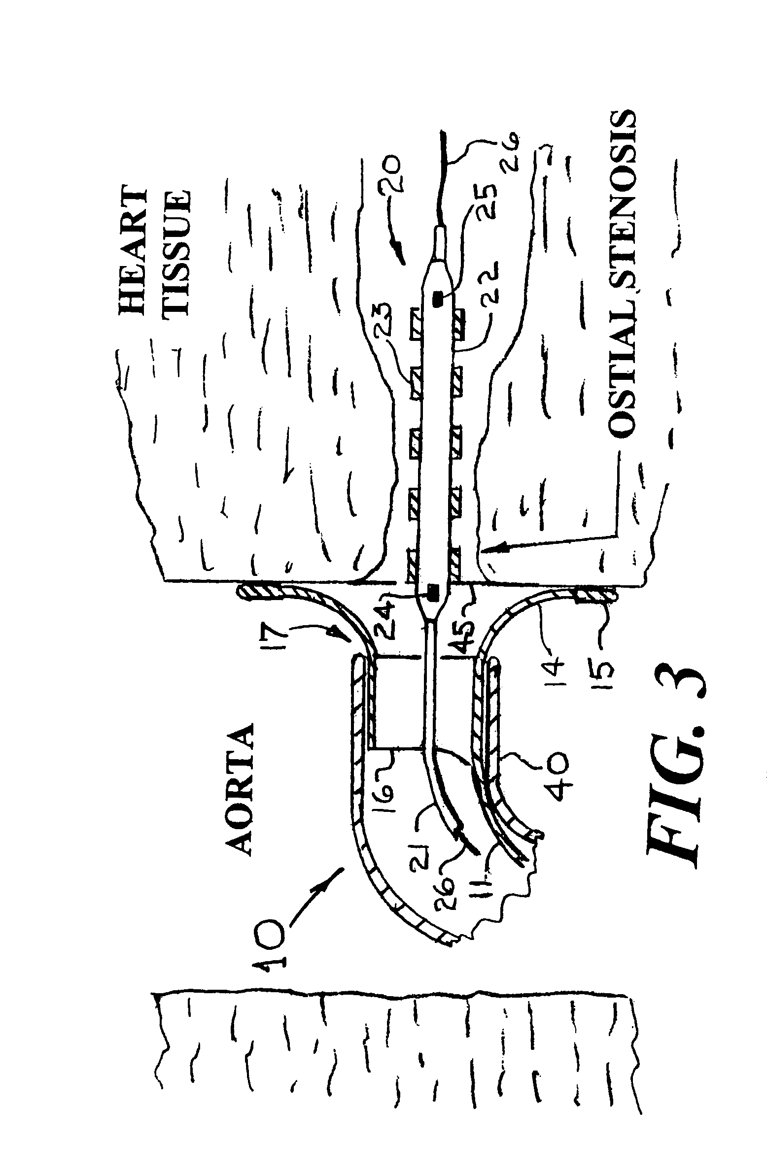
[0024]FIG. 1 is a side view of a catheter system 10 whose object is to accurately place a stent with its proximal end being situated close to the ostial plane of an artery having an ostial stenosis. The catheter system 10 includes the guiding catheter 40 and an ostial stent positioner 17 that has a wire 11 which connects a small diameter handle 12 to a cylinder 16 (shown in FIG. 2) which has expandable distal end legs 14 with radiopaque feet 15. The guiding catheter 40 that has a proximal Luer fitting 41 that is joined to a Touhy-Borst fitting 30. When the feet 15 are fully expanded, the diameter “D” would typically be between 4 and 10 mm for coronary artery stenting and between 5 and 15 mm for stenting a renal artery. When the expandable legs 14 with radiopaque feet 15 are fully expanded they would have the general appearance of the petals of a flower. When the legs 15 are pushed forward beyond the distal end of the guiding catheter 40, they expand radially outward as shown in FIGS...


PUM


Abstract

Disclosed is an ostial stent positioner that has the form of a wire for most of its length and having a short cylinder with a longitudinal slit and expandable legs situated at the positioner's distal end. The slit cylinder with its attached wire acts as an introducer sheath to introduce a stent delivery system with a stent into the artery that is to be stented. A second aspect of the present invention is a method for accurately placing a stent at the ostium of an artery that would have an ostial stenosis. Examples of such arteries that have ostial stenoses are the right and left main coronary arteries, a saphenous vein graft as used in coronary bypass surgery and the renal arteries. Also disclosed are designs for the slit cylinder that provides a variable diameter so as to fit snugly within guiding catheters having different inside diameters.

Description

REFERENCE TO A PREVIOUS PATENT APPLICATION[0001]This is a continuation-in-part application of the patent application Ser. No. 11 / 442,719 filed on May 30, 2006 now abandoned.FIELD OF USE[0002]This invention is in the field of devices for placing stents within a stenosis that extends to or near the ostium of an artery.BACKGROUND OF THE INVENTION[0003]Although most stenoses do not occur at the ostium of an artery, there are thousands of cases each month where the mouth of an artery (the ostium) is substantially obstructed at its aortic take-off; this is called an aorto-ostial lesion. In such cases, the interventional cardiologist or radiologist is frequently unable to place the stent's proximal end within ±2 mm of the ostial plane. Two types of incorrect stent positions are (1) when the stent's proximal end extends more than 2 mm into the aorta, and (2) when the stent's proximal end is placed more than 1-2 mm into the artery distal to the ostial plane.[0004]In U.S. Pat. No. 6,458,151, ...

Claims


Application Information

Patent Timeline
Patent Type & Authority Patents(United States)
IPC IPC(8): A61F2/06A61M25/01A61F2/82
CPCA61F2/95A61F2002/821A61F2250/0098
Inventor FISCHELL, ROBERT E.FISCHELL, TIM A.FISCHELL, DAVID R.ZYZELEWSKI, MARK E.
Owner MERIT MEDICAL SYST INC
Why Eureka
Try Eureka