Eureka AIR delivers breakthrough ideas for toughest innovation challenges, trusted by R&D personnel around the world.

System for generating hydrogen from a chemical hydride

a chemical hydride and hydrogen generation technology, applied in the direction of fluid pressure control, furnaces, muffle furnaces, etc., can solve the problems of unresolved problems in the production of pure hydrogen from chemical water/hydride reactions, conventional systems, methods, apparatuses, etc., to achieve the effect of reducing the cost of production

Inactive Publication Date: 2010-01-26
TRULITE INC
View PDF340 Cites 17 Cited by
  • Summary
  • Abstract
  • Description
  • Claims
  • Application Information

AI Technical Summary

Benefits of technology

[0019]In another embodiment, the liner is disposed between the housing and the liquid permeable material. The liner protects the housing from corrosion and damage.

Problems solved by technology

Producing pure hydrogen using conventional methods is generally cost prohibitive.
Unfortunately, the prior art has encountered unresolved problems producing pure hydrogen from chemical water / hydride reactions.
Specifically, conventional systems, methods, and apparatuses have not successfully controlled the chemical reaction between the water and the chemical hydride without adversely affecting the gravimetric and volumetric energy density of the overall system.
The chemical reaction between water and a chemical hydride is very severe and highly exothermic.
Many failed attempts have been made to properly control the reaction while still preserving the gravimetric and volumetric energy density provided by the chemical hydrides
Water is able to react with the outer portion of the “clump” to a certain depth, however, large portions of the “clump” remain unreacted because water cannot penetrate deeply enough into the “clump.” Consequently, the gravimetric and volumetric energy density is decreased because of the large percentage of the chemical hydride that remains unreacted.
This is inefficient and unacceptable.

Method used


Image

  • System for generating hydrogen from a chemical hydride
  • System for generating hydrogen from a chemical hydride
  • System for generating hydrogen from a chemical hydride

Examples


Embodiment Construction

[0036]Many of the functional units described in this specification have been labeled as modules, in order to more particularly emphasize their implementation independence. For example, a module may be implemented as a hardware circuit comprising custom VLSI circuits or gate arrays, off-the-shelf semiconductors such as logic chips, transistors, or other discrete components. A module may also be implemented in programmable hardware devices such as field programmable gate arrays, programmable array logic, programmable logic devices or the like.

[0037]Modules may also be implemented in software for execution by various types of processors. An identified module of executable code may, for instance, comprise one or more physical or logical blocks of computer instructions which may, for instance, be organized as an object, procedure, or function. Nevertheless, the executables of an identified module need not be physically located together, but may comprise disparate instructions stored in d...


PUM

PropertyMeasurementUnit
sizeaaaaaaaaaa
pressureaaaaaaaaaa
gas pressureaaaaaaaaaa

Abstract

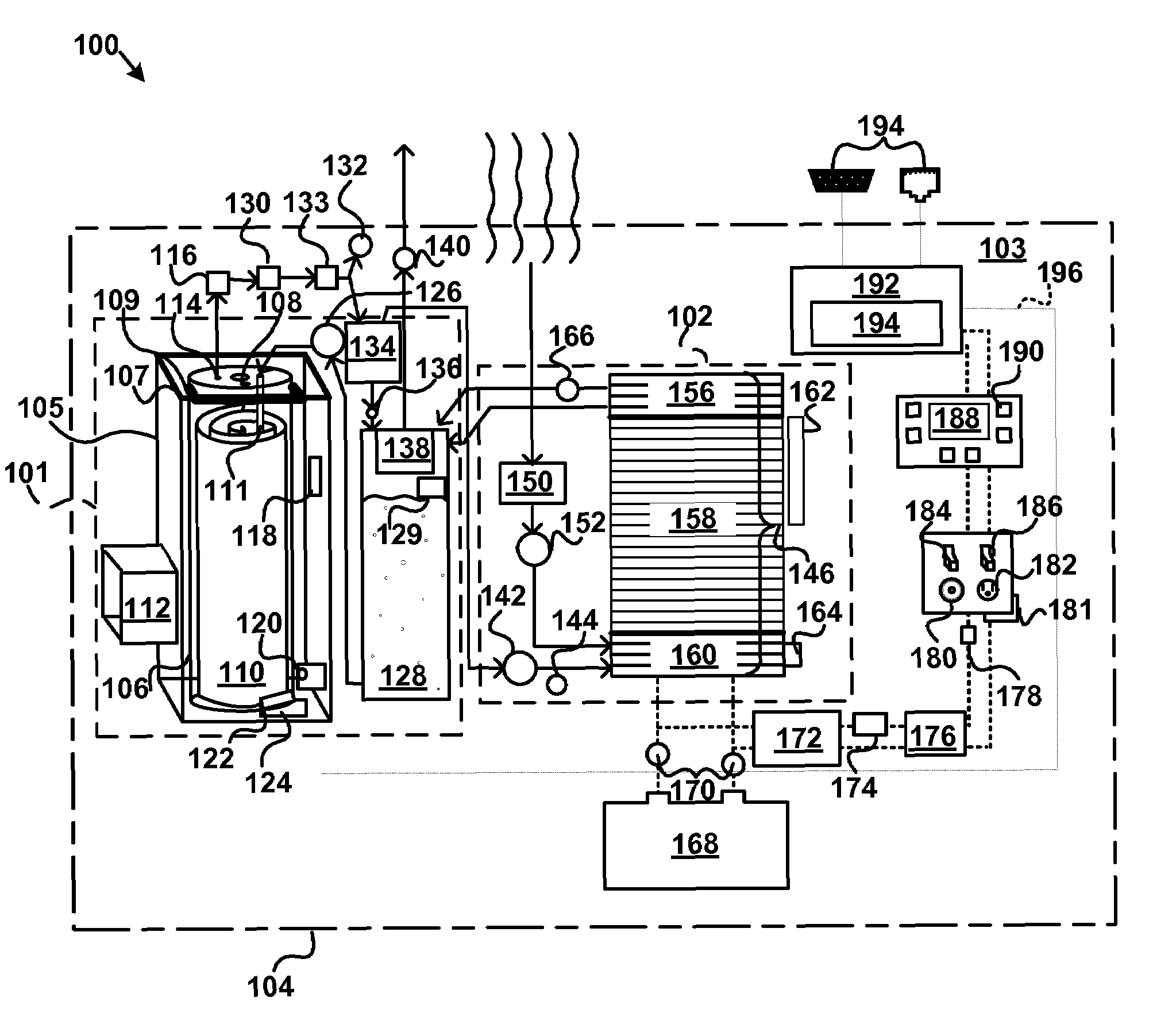
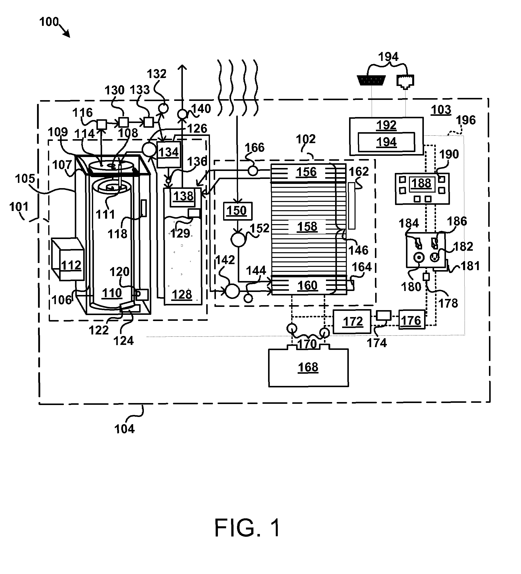
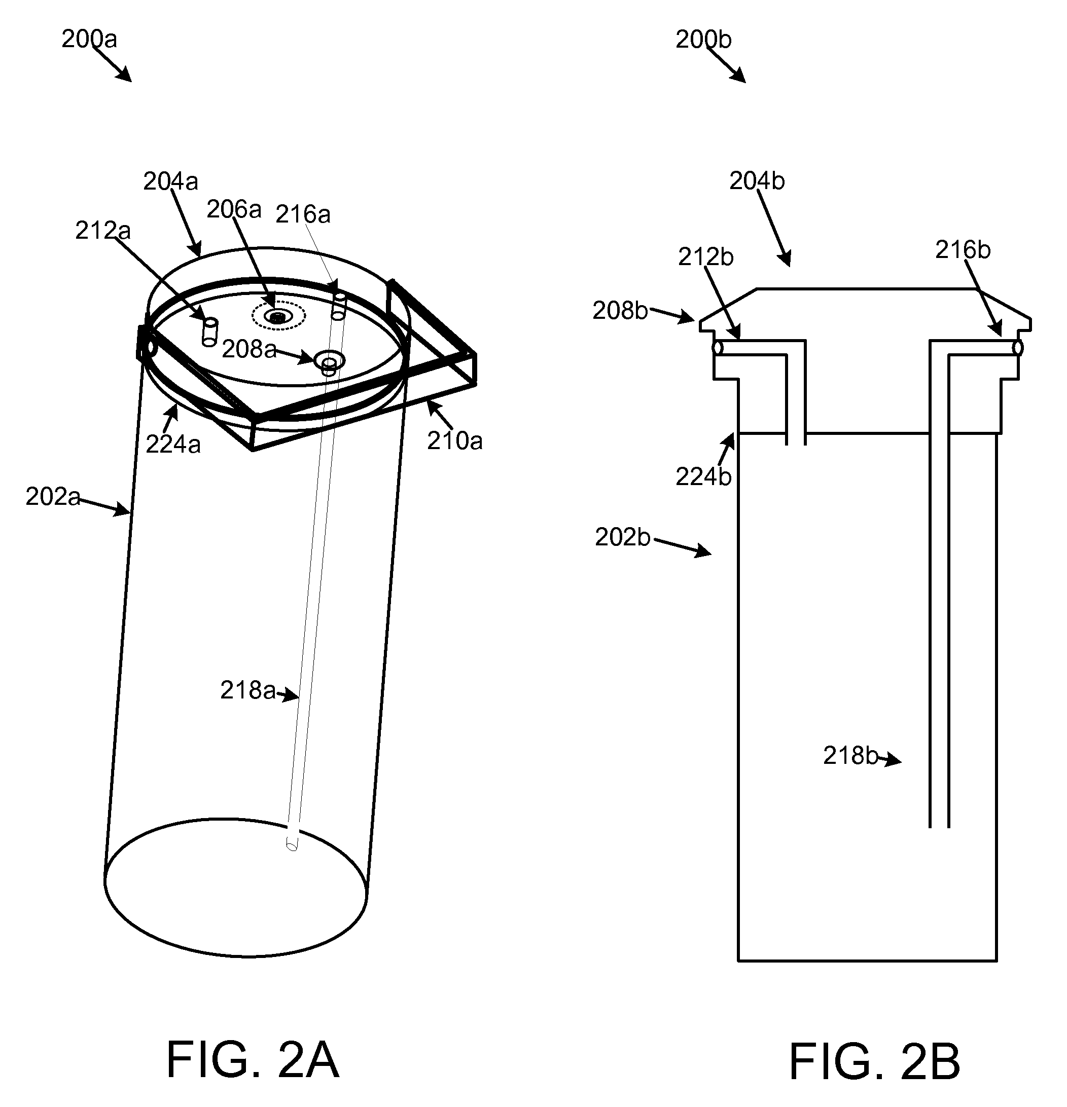
An apparatus is disclosed to generate hydrogen. A liquid permeable material with one or more cavities contains a solid anhydrous chemical hydride and an anhydrous activating agent. A housing that is heat and pressure resistant houses the liquid permeable material, and a liquid. One or more liquid sources inject the liquid into the housing such that the liquid contacts at least a portion of the liquid permeable material. A gas outlet port releases hydrogen gas produced by a reaction comprising the solid anhydrous chemical hydride, the anhydrous activating agent, and the liquid. A hydrogen output regulator controls the amount of hydrogen gas that the gas outlet port releases.

Description

CROSS-REFERENCES TO RELATED APPLICATIONS[0001]This application claims the benefit of U.S. Provisional Patent Application No. 60 / 820,574 entitled “APPARATUS, SYSTEM, AND METHOD FOR GENERATING ELECTRICITY FROM A CHEMICAL HYDRIDE” and filed on Jul. 27, 2006 for Kevin Shurtleff, et. al which is incorporated herein by reference. This application incorporates by reference U.S. Pat. Nos. 7,393,369 filed Jun. 11, 2003, U.S. Pat. No. 7,438,732 filed Nov. 12, 2005, U.S. patent application Ser. Nos. 11 / 740,349 filed Apr. 26, 2007, and U.S. patent application Ser. No. 11 / 828,265 filed Jul. 25, 2007; and U.S. Provisional Patent Applications Ser. No. 60 / 820,574 filed Jul. 27, 2006, 60 / 951,903 filed Jul. 25, 2007, 60 / 951,907 filed Jul. 25, 2007, and 60 / 951,925 filed Jul. 25, 2007, each of which is incorporated by reference herein in its entirety.BACKGROUND OF THE INVENTION[0002]1. Field of the Invention[0003]This invention relates to hydrogen generation and more particularly relates to hydrogen ge...

Claims


Application Information

Patent Timeline
Patent Type & Authority Patents(United States)
IPC IPC(8): C01B3/26C10J3/20
CPCB01J7/02B01J8/0271C01B3/065C01B2203/066Y02E60/362F17C11/005Y02E60/32Y02E60/36
Inventor SHURTLEFF, KEVINLADD, ERICPATTON, JOHNBRYDON, CHRISPEARSON, KEN
Owner TRULITE INC
Why Eureka
Eureka Blog
Learn More