Silicon-containing composite bodies, and methods for making same

a composite body and silicon technology, applied in the field of composite materials and melt infiltration methods, can solve problems such as chemical changes, and achieve the effects of reducing the melting point of infiltrants, enhancing infiltration, and ensuring the stability of the composite body

Inactive Publication Date: 2010-02-09
II VI DELAWARE INC
View PDF28 Cites 25 Cited by
  • Summary
  • Abstract
  • Description
  • Claims
  • Application Information

AI Technical Summary

Benefits of technology

[0037]Carbon is frequently added to the porous mass to enhance infiltration. (Unless otherwise noted, from hereon the term “porous mass” will be understood to include the term “preform”.) One ramification of using a multi-constituent infiltrant, however, is the change that takes place in the chemical composition of the infiltrant as it infiltrates the porous mass or preform, and specifically as the silicon constituent of the infiltrant metal reacts with the carbon contained therein to produce silicon carbide. Accordingly, the present inventors have discovered the significance and importance of keeping the reactable or “free” carbon content of the porous mass to be infiltrated at relatively low levels. Preferably, the amount of free carbon in the porous mass is kept as low as necessary to accomplish complete infiltration in a reliable manner but without unduly compromising the binder qualities of the carbon when preforms (e.g., self-supporting porous masses) are used. This way, large bodies can be infiltrated with minimal changes in the infiltrant metal's composition, thereby resulting in a silicon carbide composite body having a dispersed residual metal component of relatively uniform composition throughout the body.
[0038]The use of a multi-constituent infiltrant composition has additional advantages beyond the ability to produce composite bodies whose residual metal component has zero or near-zero volumetric change (swelling or contraction) upon solidification.
[0039]For instance, and in another major aspect of the present invention, the alloying of silicon infiltrant with one or more different elemental constituents can substantially depress the melting point of the infiltrant. Desirable alloying elements in this regard include aluminum, beryllium, copper, cobalt, iron, manganese, nickel, tin, zinc, silver and gold. The lowered melting or liquidus temperatures permit the infiltration to be conducted at lower temperatures. For example, when the infiltrant comprises a silicon-aluminum alloy, it is possible to infiltrate a porous mass comprising some elemental carbon at a temperature in the range of about 11000 to about 1300° C. By

Problems solved by technology

One ramification of using a multi-constituent infiltrant, however, is the change that takes place in the chemical composition of the infiltrant as it infiltrates t

Method used


Image

  • Silicon-containing composite bodies, and methods for making same
  • Silicon-containing composite bodies, and methods for making same
  • Silicon-containing composite bodies, and methods for making same

Examples


reference example 1

No Alloying

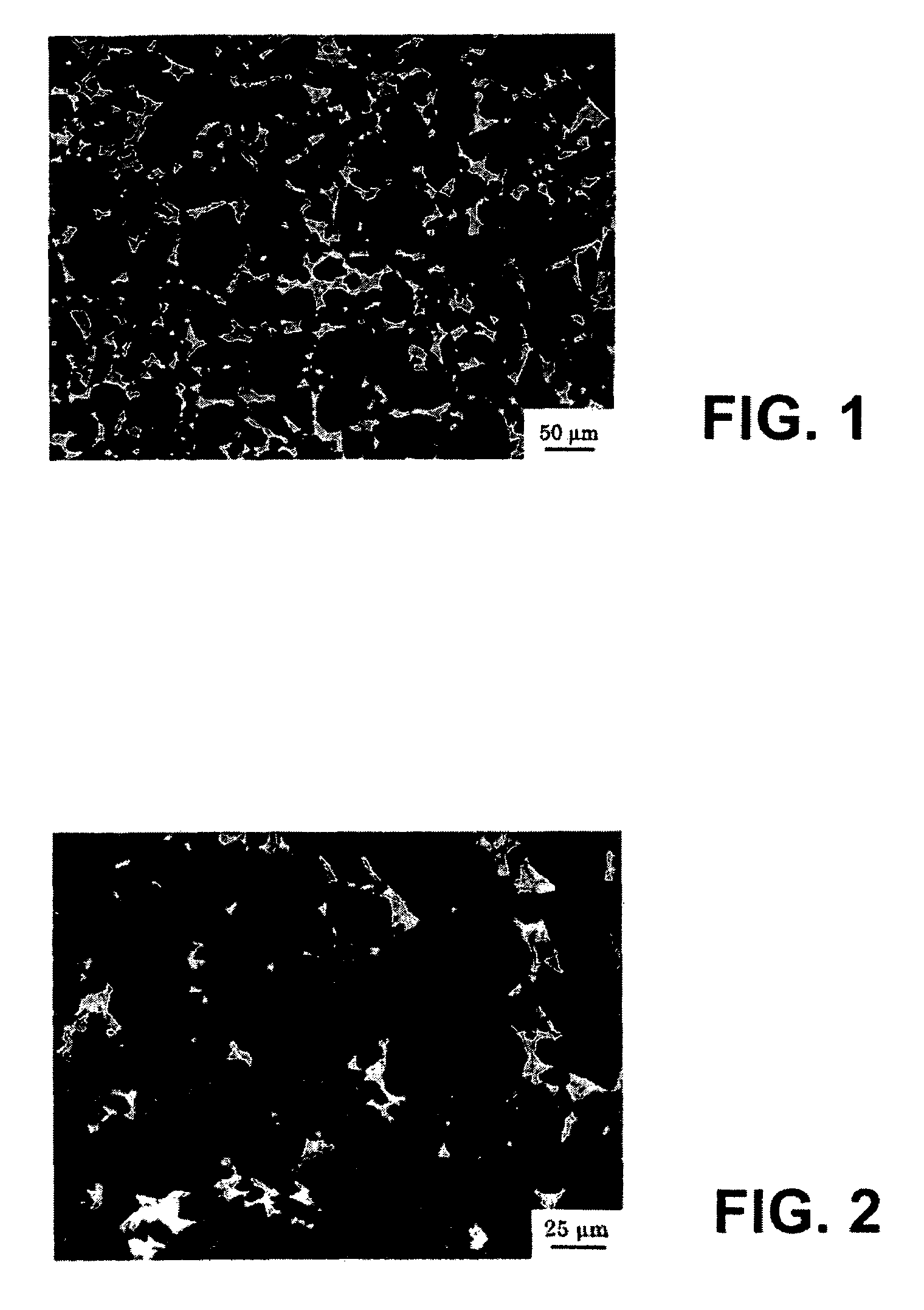
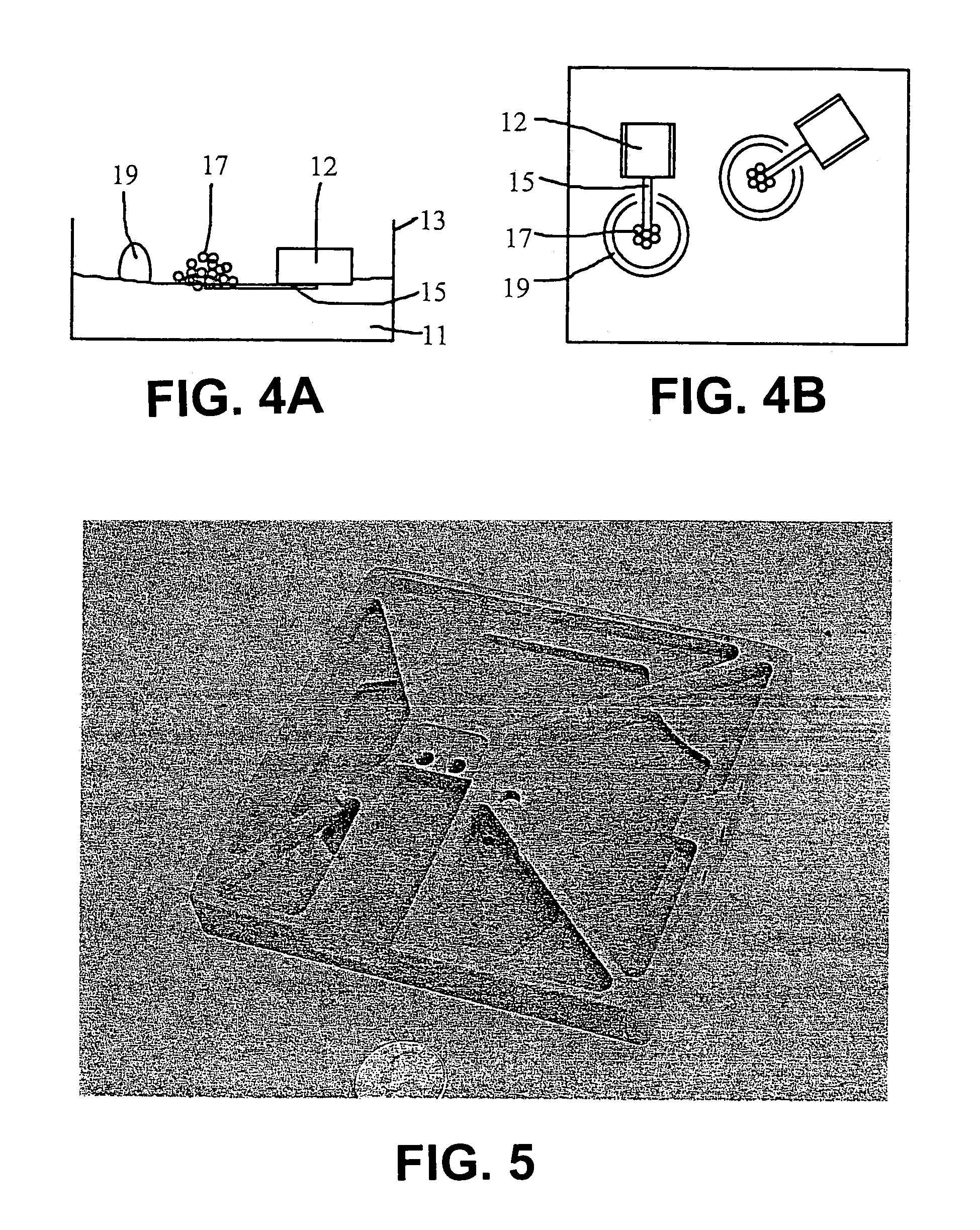
[0108]This example demonstrates the production of a reaction bonded Si / SiC composite body. More specifically, this Example demonstrates the infiltration of substantially pure silicon into a silicon carbide preform containing an interconnected carbon phase derived from a resinous precursor.

[0109]First, a preform was prepared as follows. One hundred parts by weight of CRYSTOLON blocky (regular), green silicon carbide particulate (St. Gobain / Norton Industrial Ceramics, Worchester, Mass.) was combined with fifteen parts of Karo corn syrup (CPC International Inc., Englewood Cliffs, N.J.) by mixing. The silicon carbide particulate content consisted of about 70 percent having a median particle size of about 56 microns (Grade F 240), and the balance having a median particle size of about 13 microns (Grade F 500). The mixing was conducted in a Model RV02 Eirich high shear mixer as follows: First the SiC particulates were mixed for 2 minutes on the “low” speed. Then half the corn s...

example 2

[0117]The technique of Example 1 was repeated, with a major change being that the infiltrant featured aluminum substituted for about half of the mass of silicon. Thus, excluding impurities, the infiltrant was about 50 percent by weight silicon and about 50 percent aluminum. Also, in this Example the infiltration was conducted at a lower temperature than in Example 1.

[0118]The masses of the preform and infiltrant were slightly different from those of Example 1, at 44.8 grams and 20 grams, respectively. As for the differences in the heating schedule, the lay-up of the present Example was heated in vacuo from about ambient temperature to a temperature of about 1000° C. at a rate of about 200° C. per hour. After maintaining a temperature of about 1000° C. for about 1 hour, the temperature was further increased to a temperature of about 1150° C. at a rate of about 150° C. per hour. After maintaining a temperature of about 1150° C. for about 4 hours, the lay-up was cooled to near-ambient ...

example 3

[0120]This example demonstrates the effect of infiltrant chemistry on some selected physical properties of a silicon carbide composite body.

[0121]Two identical preforms were made using the materials and procedures similar to those detailed in Example 1. Following pyrolysis, each preform comprised by volume about 70 percent SiC and by weight about 3 percent elemental carbon.

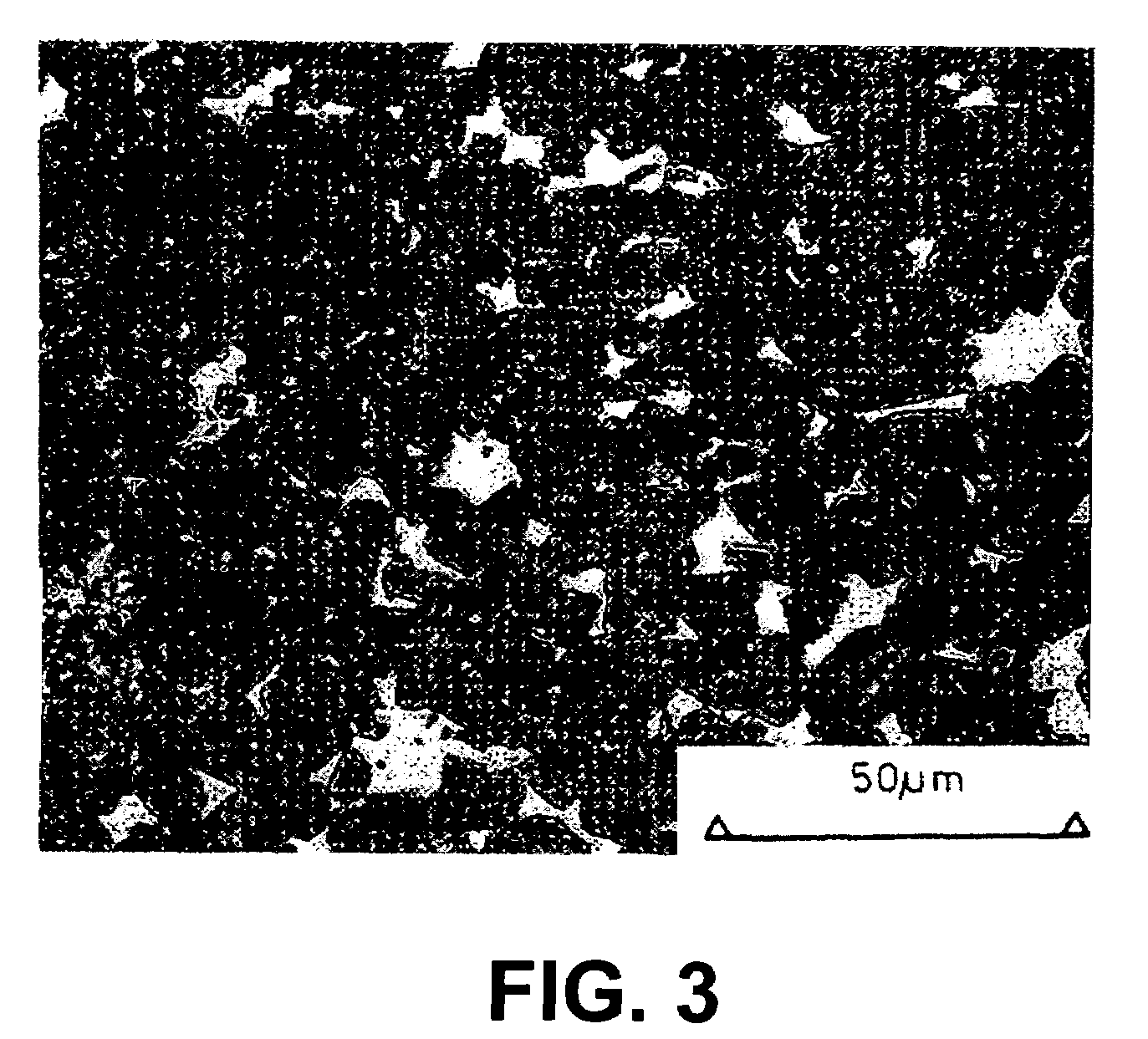
[0122]One of the preforms, Sample A, was infiltrated according to the infiltrant composition and thermal processing schedule detailed in Example 1. The other preform, Sample B, was infiltrated according to the infiltrant composition and thermal processing schedule described in Example 2. Thus, Sample A was infiltrated with nominally pure silicon, and Sample B was infiltrated with nominally Si-50Al alloy. Following infiltration, the resulting SiC composite bodies were characterized. Selected properties are provided in Table I.

[0123]

TABLE IPropertyTestSample ASample BSiC content (vol. %)QIA73+ / −376+ / −2Density (g / cc)...


PUM

PropertyMeasurementUnit
Fractionaaaaaaaaaa
Percent by volumeaaaaaaaaaa

Abstract

Composite bodies made by a silicon metal infiltration process that feature a metal phase in addition to any residual silicon phase. Not only does this give the composite material engineer greater flexibility in designing or tailoring the physical properties of the resulting composite material, but the infiltrant also can be engineered compositionally to have much diminished amounts of expansion upon solidification, thereby enhancing net-shape-making capabilities. These and other consequences of engineering the metal component of composite bodies made by silicon infiltration permit the fabrication of large structures of complex shape. Certain liquid-based preforming techniques are particularly well suited to the task, particularly where a high volumetric loading of the reinforcement component is desired.

Description

CROSS-REFERENCE TO RELATED APPLICATIONS[0001]This patent document is a Continuation-in-Part of co-pending U.S. patent application Ser. No. 10 / 336,626, filed on Jan. 3, 2003, which is a Divisional of U.S. patent application Ser. No. 09 / 621,562, filed on Jul. 21, 2000, which issued as U.S. Pat. No. 6,503,572 on Jan. 7, 2003. This patent document also claims the benefit of U.S. Provisional Patent Application No. 60 / 623,485, filed on Oct. 30, 2004. The entire contents of each of these commonly owned patent applications is incorporated herein by reference.BACKGROUND OF THE INVENTION[0002]1. Field of the Invention[0003]The present invention relates to improved composite materials and the melt infiltration methods for producing the same. Specifically, the present invention relates to silicon-based composites wherein potentially large components of potentially complex shape can be made accurate dimensionally, reliably, and utilizing relatively low processing temperatures. In a preferred emb...

Claims


Application Information

Patent Timeline
IPC IPC(8): C22C29/00
CPCC04B35/565C04B35/573C04B35/62655C04B41/009C04B41/4584C04B41/5022C04B41/5089C04B41/85C04B41/86C22C1/1005C22C1/1036C22C29/065C22C47/04C04B41/4539C04B41/5041C04B41/5031C04B33/00C04B35/10C04B35/46B22F3/11B22F3/26B22F2998/10C04B2111/00827C04B2235/3826C04B2235/40C04B2235/402C04B2235/404C04B2235/405C04B2235/407C04B2235/408C04B2235/428C04B2235/5436C04B2235/5472C04B2235/604C04B2235/728C04B2235/77C04B2235/80C04B2235/96C04B2235/9607C22C2001/1057C22C1/1057
Inventor WAGGONER, W. MICHAELROSSING, BARRY RROSSING, LEGAL REPRESENTATIVE, MARLENERICHMOND, MICHAEL AAGHAJANIAN, MICHAEL KMCCORMICK, ALLYN L
Owner II VI DELAWARE INC
Why Eureka
Try Eureka