Output power factor control of pulse-width modulated inverter

a technology of output power factor and inverter, which is applied in the direction of electric variable regulation, process and machine control, instruments, etc., can solve the problems of increasing the complexity and cost of supplying power to the grid, not being used, and damage to equipmen

Active Publication Date: 2010-02-09
SCHNEIDER ELECTRIC SOLAR INVERTERS USA
View PDF7 Cites 62 Cited by
  • Summary
  • Abstract
  • Description
  • Claims
  • Application Information

AI Technical Summary

Problems solved by technology

A photovoltaic panel or a plurality of such panels, known as an array, can produce more energy than may be required or demanded therefrom and thus while energy is available, it may not be used.
However, such implementations usually lack a cycle-by-cycle overcurrent protection loop, enabling an overcurrent condition to exist for an unacceptably long period of time, which can damage equipment.
Analog or hybrid analog / digital designs typically require the use of two separate analog multipliers associated with respective phases of the AC waveform, each of which introduces errors into their product by different amounts, which tends to introduce a DC offset current to the output AC waveform, requiring additional compensation circuitry which can increase the complexity and cost of supplying power to the grid.

Method used


Image

  • Output power factor control of pulse-width modulated inverter
  • Output power factor control of pulse-width modulated inverter
  • Output power factor control of pulse-width modulated inverter

Examples


Embodiment Construction

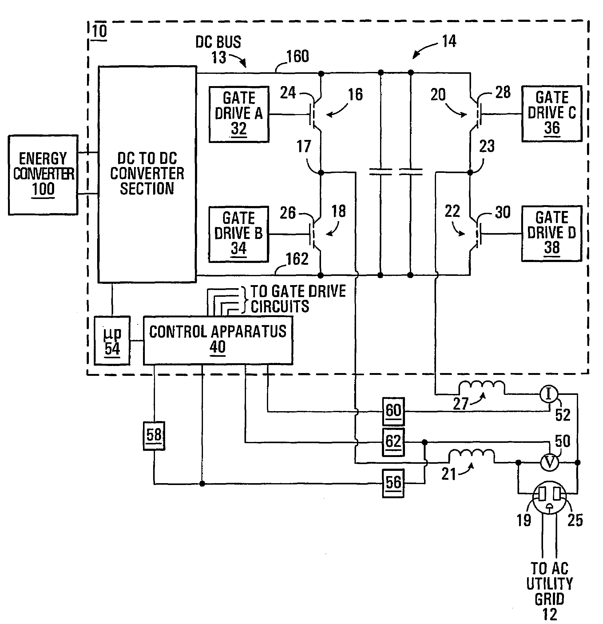
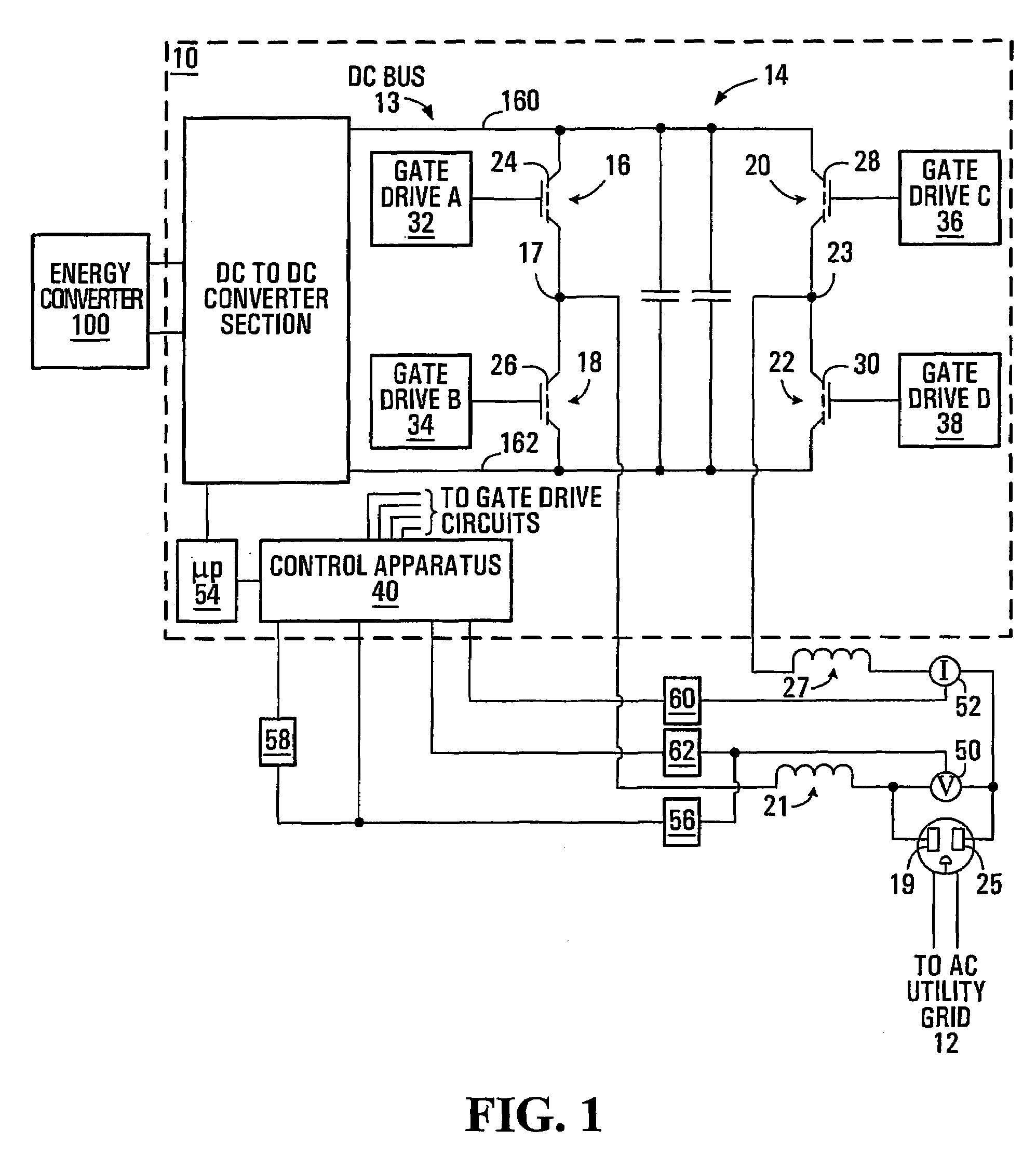
[0050]Referring to FIG. 1, an inverter configured to supply power to a load at a high power factor is shown generally at 10. The load may include an AC utility grid 12. In the embodiment shown, the inverter 10 supplies power to the grid 12 at substantially unity power factor.

[0051]The inverter 10 includes a DC bus 13 supplied with energy from a DC source. The DC bus has first and second terminals including a positive terminal 160 and a negative terminal 162. The inverter also includes a full bridge-type DC to AC converter section 14 having first, second, third and fourth switching legs 16, 18, 20 and 22 connected to the first and second terminals 160 and 162 of the DC bus as shown. Each switching leg 16, 18, 20 and 22 may include one or more switches, which, in the embodiment shown, include respective metallic oxide semiconductor field effect transistors (MOSFETs) 24, 26, 28 and 30.

[0052]The first and second switching legs 16 and 18 are connected together at a first node 17 that is ...


PUM


Abstract

An inverter operable to supply high power factor electrical power to an AC load including an AC power grid includes a DC bus and a DC to AC converter section of the full bridge type. The inverter further includes a voltage sensor configured to produce an instantaneous output voltage signal representing instantaneous output voltage of the inverter, a rectification circuit configured to produce a rectified output voltage signal, a power signal generator, an output current sensor configured for sensing an output current of the inverter, a rectification circuit configured to produce the rectified output current signal, a sign circuit for producing a signal representing the sign of the output voltage and a control apparatus. The control apparatus includes a scaled rectified voltage signal generator, a pulse width modulation (PWM) signal generator configured to produce a pulse width modulation signal in response to the scaled rectified voltage signal and the rectified output current signal and a switching leg controller circuit configured to control the full bridge switches.

Description

BACKGROUND OF THE INVENTION[0001]1. Field of Invention[0002]This invention relates to supplying power to an alternating current (AC) load, particularly an AC grid, from a direct current (DC) source. More particularly, the invention relates to methods and apparatus for controlling switching legs of a switching circuit of an inverter to supply high power factor electrical power to a load.[0003]2. Description of Related Art[0004]As energy demands of consumers and industry increase, alternative forms of energy are becoming increasingly accepted and developed. One of these alternative forms of energy is solar energy. Solar energy is often harvested through the use of one or more photovoltaic panels, which produce direct current (DC) power from the sun's energy. The sun's energy impinges upon a photovoltaic panel and can provide a readily available energy source in climates subject to high amounts of solar radiation. A photovoltaic panel or a plurality of such panels, known as an array, c...

Claims


Application Information

Patent Timeline
Patent Type & Authority Patents(United States)
IPC IPC(8): H02M7/162G05F1/70H02M1/12H02M7/5387
CPCH02M1/12H02M7/53871Y02B70/10
Inventor GARABANDIC, DJORDJE
Owner SCHNEIDER ELECTRIC SOLAR INVERTERS USA
Why Eureka
Try Eureka