
Central control system and method for controlling air conditioners

Inactive Publication Date: 2010-02-16
LG ELECTRONICS INC
View PDF30 Cites 44 Cited by
  • Summary
  • Abstract
  • Description
  • Claims
  • Application Information

AI Technical Summary

Benefits of technology

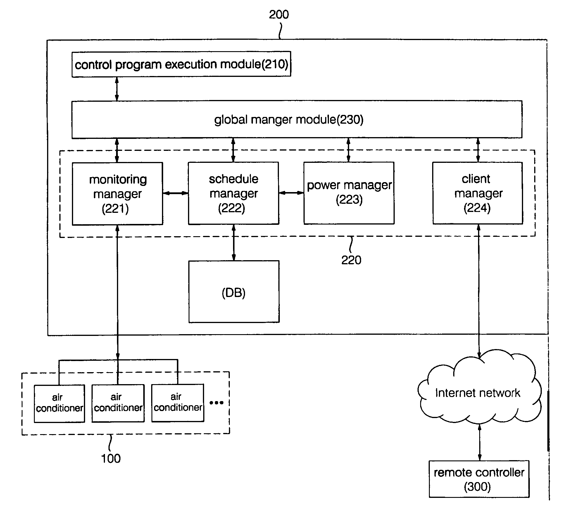
[0012]Therefore, the present invention has been made in view of the above problems, and it is an object of the present invention to provide a central control system and method for controlling air conditioners, which can control the air conditioners according to an operation schedule or control command inputted from a central controller capable of performing central control operations for the air conditioners or a remote controller coupled to the central controller through an Internet network so that a control range can be extended.
[0013]It is another object of the present invention to provide a central control system and method for controlling air conditioners, which can perform an integrated schedule management operation using a central controller in which a control program is executed so that an operation schedule of the air conditioners can be inputted / edited / confirmed.
[0014]It is yet another object of the present invention to provide a central control system and method for controlling air conditioners, which can automatically adjust an operation schedule to prevent consumption of electric power from abruptly increasing when the air conditioners are simultaneously operated, and perform a stable power management operation.
[0016]In accordance with another aspect of the present invention, there is provided a method for controlling air conditioners in a central control system, comprising the steps of: (a) transmitting, to the air conditioners, an operation schedule and a control command inputted through a central controller capable of performing central control operations for the air conditioners, and simultaneously monitoring operating states of the air conditioners; (b) generating control signals so that the air conditioners can be operated in response to the operation schedule and control command inputted at the step (a); and (c) adjusting time intervals between operations of the air conditioners to manage electric power consumption.

Problems solved by technology

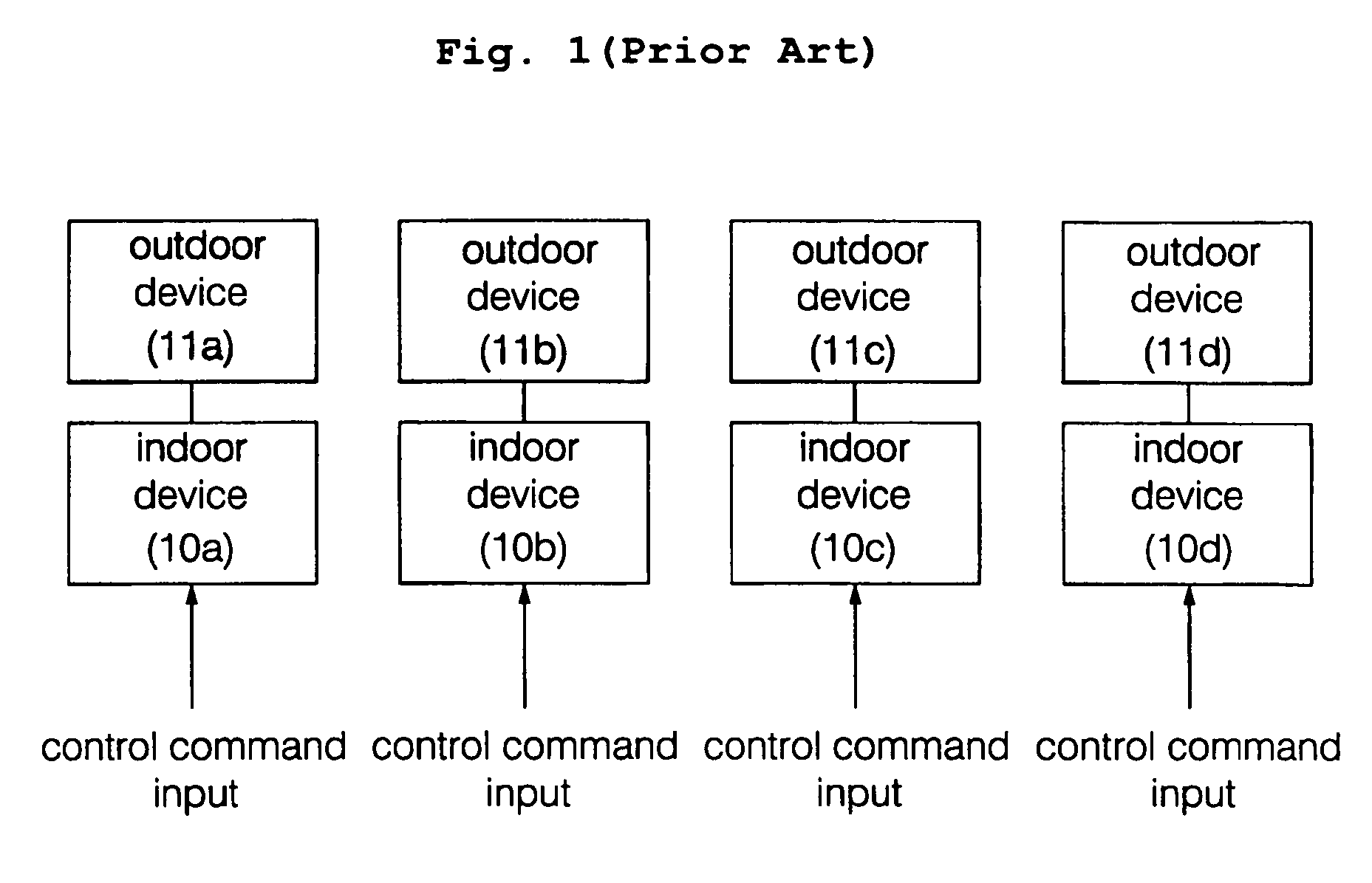
Where the multiple indoor devices 10a, 10b, 10c and 10d are installed on each of stories within a large-sized building, respectively, there is a drawback in that manpower and cost for managing the air conditioners increase significantly.
However, there are problems in that a physical control range within which the air conditioners may be controlled is extremely limited and hence the air conditioners cannot be conveniently controlled.
In particular, where power supplies of the air conditioners requiring a significant amount of electric power are simultaneously turned on, the load of electric power is abruptly increased within the building equipped with the air conditioners and hence a power circuit breaker may not appropriately operate.
At this time, other electric devices also cannot be used.
Of course, since problems such as an operating error, data loss, etc. can be caused by an operation error of the power circuit breaker, it must be noted that the large number of air conditioners cannot be simultaneously operated.
However, the number of buttons formed on the conventional remote controller for the air conditioner is limited.
Since a procedure of inputting an operation schedule is complicated, there are problems in that an operator's manual must be referred to and the increased number of manipulations is needed to input the operation schedule.
Since the remote controller is not equipped with a liquid crystal display (LCD), or a size of the LCD arranged on the remote controller is small, it is difficult for time information of the operation schedule to be confirmed.

Method used


Image

  • Central control system and method for controlling air conditioners
  • Central control system and method for controlling air conditioners
  • Central control system and method for controlling air conditioners

Examples


Embodiment Construction

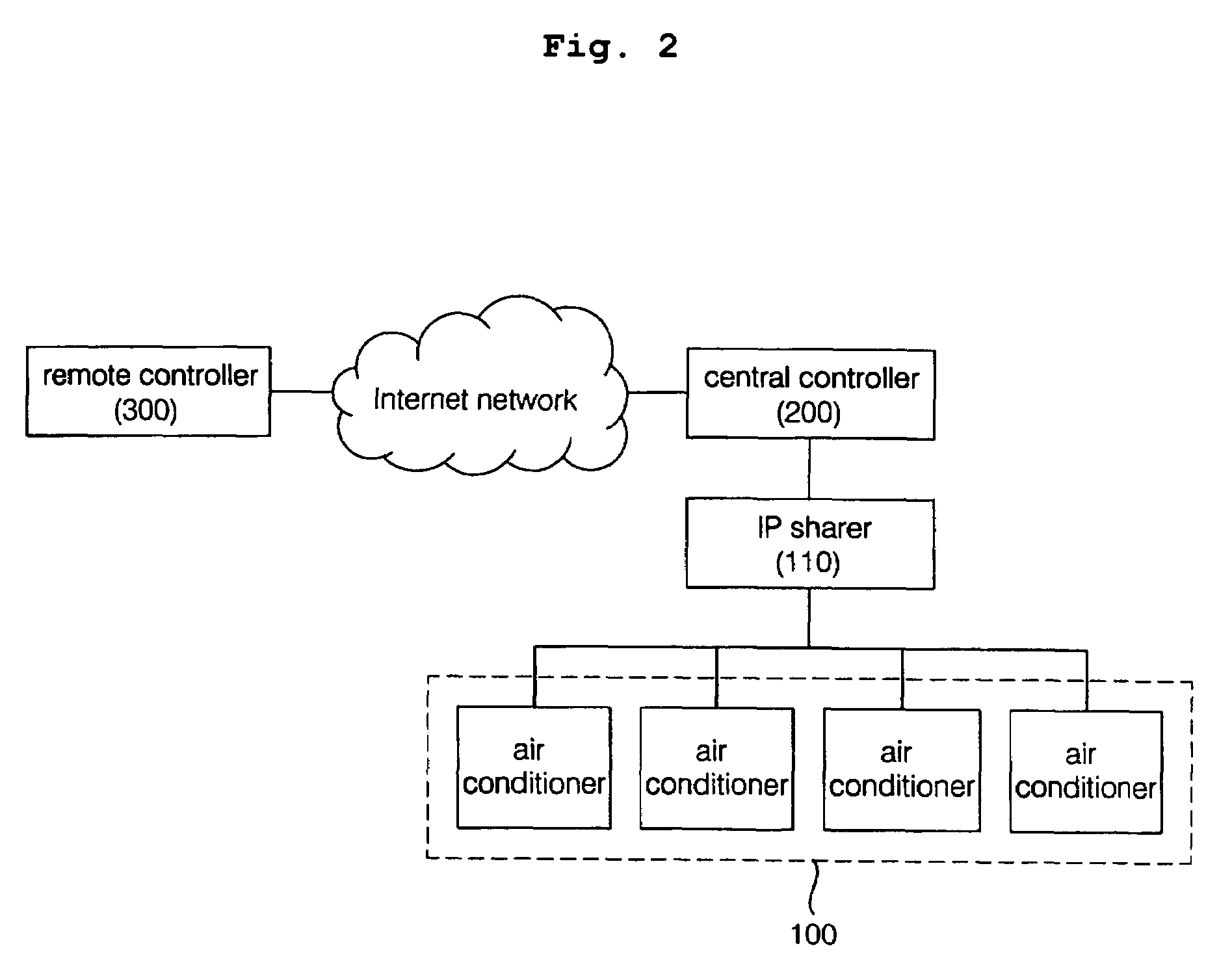
[0025]First, the configuration of a central control system for controlling air conditioners will be described in detail with reference to FIG. 2.

[0026]A system of air conditioners including a plurality of indoor devices and a plurality of outdoor devices installed in each room of a general home or in each office room within a building is referred to as a single-type air conditioner system. Further, a system of air conditioners including a single outdoor device and a plurality of indoor devices sharing the single outdoor device installed in each room of a general home or in each office room within a building is referred to as a multi-type air conditioner system. Hereinafter, the air conditioners included in the above-described air conditioner systems are referred to as a plurality of air conditioners 100. Further, the air conditioners can include not only an air conditioner for performing a cooling operation, but also a heat-pump-type air conditioner for performing a cooling or heati...


PUM


Abstract

A central control system and method for controlling air conditioners. The central control system performs central control operations for the air conditioners according to an operation schedule or control command inputted from a central controller coupled to the air conditioners through an internal network or a remote controller accessible to an external Internet network. When the air conditioners are simultaneously operated, control signals based on the control command are adjusted to prevent electric power consumption from abruptly increasing and hence the stability and reliability of control can be improved. The central controller includes a touch screen-based monitor. A control program included in the central controller provides a timetable corresponding to a specified period. An operator can conveniently input / edit the operation schedule through a dragging operation performed on the monitor, and confirm the inputted / edited operation schedule.

Description

BACKGROUND OF THE INVENTION[0001]1. Field of the Invention[0002]The present invention relates to a central control system and method for controlling air conditioners, which can perform central control operations for the air conditioners according to an operation schedule or control command inputted from a central controller coupled to the air conditioners through an internal network or a remote controller accessible to an external Internet network, and automatically adjust the operation schedule to appropriately supply electric power to the air conditioners.[0003]2. Description of the Related Art[0004]As the use of air conditioners has remarkably increased, a single-type air conditioner system configured by a plurality of indoor devices 10a, 10b, 10c and 10d and a plurality of outdoor devices 11a, 11b, 11c and lid has been installed in each room of a general home or in each office room within a building. Further, a multi-type air conditioner system configured by a single outdoor dev...

Claims


Application Information

Patent Timeline
IPC IPC(8): G05D23/00F24F11/02F24F11/00
CPCF25B2700/05F24F11/30F24F11/62F24F11/54F24F11/58
Inventor YOON, SANG CHULJEON, DUCK GUJUNG, JAE SIKKWON, JAE HWAN
Owner LG ELECTRONICS INC
Learn More